 |
ac5wzw00007962
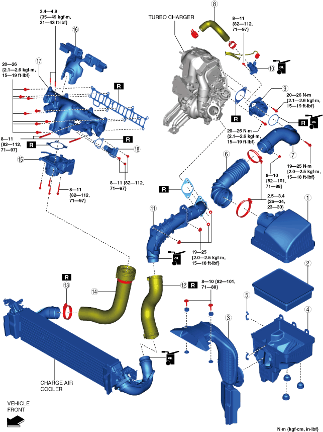
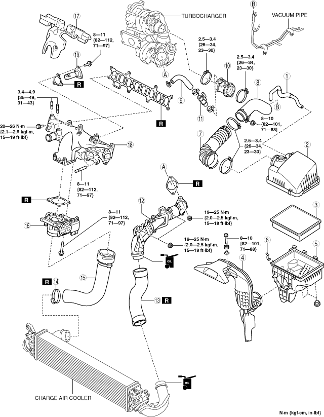
INTAKE-AIR SYSTEM REMOVAL/INSTALLATION [SKYACTIV-D 2.2]
id0113z7801900
Fuel injector ( 2pin type)
|
Gasket
Quantity: 1
Location of use: Turbocharger air outlet pipe component
|
Charge air cooler air inlet hose
Quantity: 1
Location of use: Turbocharger air outlet pipe component
|
Hose clamp
Quantity: 1
Location of use: Charge air cooler air outlet hose
|
|
Gasket
Quantity: 1
Location of use: Intake air shutter valve
|
Intake manifold gasket
Quantity: 1
Location of use: Intake manifold
|
Gasket
Quantity: 1
Location of use: EGR pipe (intake manifold side)
|
Fuel injector ( 6pin type)
|
Gasket
Quantity: 1
Location of use: Turbocharger air outlet pipe component
|
Charge air cooler air inlet hose
Quantity: 1
Location of use: Turbocharger air outlet pipe component
|
Hose clamp
Quantity: 1
Location of use: Charge air cooler air outlet hose
|
|
Gasket
Quantity: 1
Location of use: Intake air shutter valve
|
Intake manifold gasket
Quantity: 1
Location of use: Intake manifold
|
Gasket
Quantity: 1
Location of use: EGR pipe (intake manifold side)
|
|
Gasket
Quantity: 1
Location of use: Turbocharger air inlet pipe
|
O-ring
Quantity: 1
Location of use: Turbocharger air inlet pipe
|
—
|
Oil and Chemical Type
|
Engine oil
Type: Recommended oil
|
1. Disconnect the negative battery terminal. (See NEGATIVE BATTERY TERMINAL DISCONNECTION/CONNECTION.)
2. Remove in the order shown in the figure.
3. Install in the reverse order of removal.
Fuel injector (2pin type)
ac5wzw00007962
|
|
1
|
Vacuum hose
|
|
2
|
Air cleaner cover
|
|
3
|
Air cleaner element
|
|
4
|
Fresh-air duct
|
|
5
|
Air cleaner case
|
|
6
|
Clip
|
|
7
|
Air hose
(See Air Hose Installation Note.)
|
|
8
|
Air inlet pipe
|
|
9
|
Breather hose
|
|
10
|
Turbocharger air inlet hose
|
|
11
|
Blow-by heater
|
|
12
|
Turbocharger air outlet pipe component
|
|
13
|
Charge air cooler inlet hose
|
|
14
|
Hose clamp
(See Hose Clamp Removal Note.)
(See Hose Clamp Installation Note.)
|
|
15
|
Charge air cooler outlet hose
|
|
16
|
Intake shutter valve
|
|
17
|
Intake manifold insulator
|
|
18
|
Intake manifold
|
|
19
|
EGR pipe (Intake manifold side)
|
Fuel injector (6pin type)
ac5wzw00012055
|
|
1
|
Air cleaner cover
|
|
2
|
Air cleaner element
|
|
3
|
Fresh-air duct
|
|
4
|
Air cleaner case
|
|
5
|
Clip
|
|
6
|
Air hose
(See Air Hose Installation Note.)
|
|
7
|
Air inlet pipe
|
|
8
|
Breather hose
(See Breather Hose Removal Note.)
|
|
9
|
Turbocharger air inlet pipe
|
|
10
|
Blow-by heater
|
|
11
|
Turbocharger air outlet pipe component
|
|
12
|
Charge air cooler inlet hose
|
|
13
|
Hose clamp
(See Hose Clamp Removal Note.)
(See Hose Clamp Installation Note.)
|
|
14
|
Charge air cooler outlet hose
|
|
15
|
Intake shutter valve
|
|
16
|
Intake manifold insulator
|
|
17
|
Intake manifold
|
|
18
|
EGR pipe (Intake manifold side)
|
Air Cleaner Cover Removal Note
1. Remove the MAF sensor/IAT sensor No.1. (See MASS AIR FLOW (MAF) SENSOR/INTAKE AIR TEMPERATURE (IAT) SENSOR NO.1 REMOVAL/INSTALLATION [SKYACTIV-D 2.2].)
2. Remove the air cleaner cover.
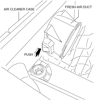
Fresh-air Duct Removal Note (Fuel injector (2pin type))
1. Pull out the fresh-air duct from the air cleaner case while pressing the tab shown in the figure.
ac5wzw00005680
|
Fresh-air Duct Removal Note (Fuel injector (6pin type))
1. While moving the tabs in the direction shown in the figure, rotate the fresh air duct.
ac5wzw00012056
|
2. Remove the fresh-air duct.
Air Inlet Pipe Removal Note (Fuel injector (2pin type))
1. Remove the battery. (See BATTERY REMOVAL/INSTALLATION [SKYACTIV-D 2.2].)
2. Remove the air inlet pipe.
Air Inlet Pipe Removal Note (Fuel injector (6pin type))
1. Remove the battery and the battery tray. (See BATTERY REMOVAL/INSTALLATION [SKYACTIV-D 2.2].)
2. Remove the air inlet pipe.
Turbocharger Air Outlet Pipe Component Removal Note
1. Remove the battery tray. (See BATTERY REMOVAL/INSTALLATION [SKYACTIV-D 2.2].)
2. Remove the turbocharger air outlet pipe component.
Breather Hose Removal Note
1. Remove the engine cover. (See ENGINE COVER REMOVAL/INSTALLATION [SKYACTIV-D 2.2].)
2. Remove the breather hose.
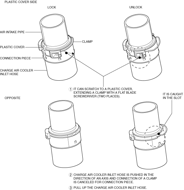
Charge Air Cooler Inlet Hose Removal Note
1. Release the lock and remove the charge air cooler inlet hose as shown in the figure.
ac5uuw00010795
|
Hose Clamp Removal Note
1. Remove the front under cover No.1 and the front under cover No.2. (See FRONT UNDER COVER No.1 REMOVAL/INSTALLATION.) (See FRONT UNDER COVER No.2 REMOVAL/INSTALLATION.)
2. Remove the hose clamp.
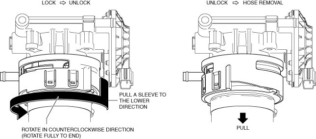
Charge Air Cooler Outlet Hose Removal Note
1. Release the lock of connector and remove the charge air cooler outlet hose.
ac5uuw00010796
|
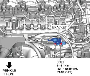
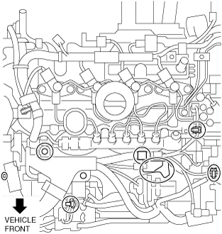
Intake Manifold Insulator Removal Note (Fuel injector (2pin type))
1. Remove the harness bracket shown in the figure.
ac5wzw00008970
|
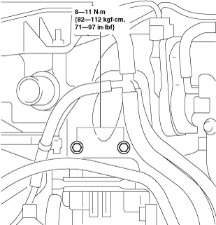
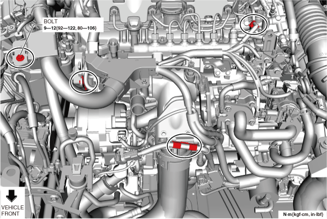
2. Remove the bolts shown in the figure.
ac5wzw00005683
|
3. Remove the intake manifold insulator.
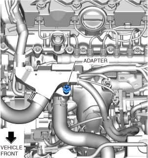
Intake Manifold Insulator Removal Note (Fuel injector (6pin type))
1. Remove the adapter shown in the figure.
ac5wzw00012057
|
2. Remove the nuts shown in the figure.
ac5wzw00012058
|
3. Disconnect the IAT sensor No.2 connector. (See INTAKE AIR TEMPERATURE (IAT) SENSOR NO.2 REMOVAL/INSTALLATION [SKYACTIV-D 2.2].)
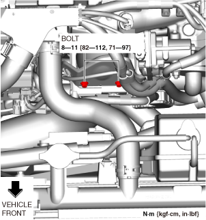
4. Remove the bolts shown in the figure.
ac5wzw00012059
|
5. Disconnect the wiring harness clips shown in the figure.
ac5wzw00012060
|
6. Remove the bolts shown in the figure.
ac5wzw00012061
|
7. Remove the intake manifold insulator.
Intake Manifold Removal Note (Fuel injector (2pin type))
1. Disconnect the connectors of the following parts:
2. Remove the wiring harness clips, bolts, nuts and harness bracket shown in the figure.
ac5wzw00005684
|
3. Disconnect the upper radiator hose from the intake manifold side.
4. Remove the EGR valve. (See EGR VALVE REMOVAL/INSTALLATION [SKYACTIV-D 2.2].)
5. Set the EGR cooler out of the way. (See EGR COOLER REMOVAL/INSTALLATION [SKYACTIV-D 2.2].)
6. Set the EGR cooler bypass valve out of the way. (See EGR COOLER BYPASS VALVE REMOVAL/INSTALLATION [SKYACTIV-D 2.2].)
7. Remove the intake manifold.
Intake Manifold Removal Note (Fuel injector (6pin type))
1. Disconnect the connectors of the following parts:
2. Remove the wiring harness clips, bolts, nuts and harness bracket shown in the figure.
ac5wzw00012062
|
3. Remove the EGR valve. (See EGR VALVE REMOVAL/INSTALLATION [SKYACTIV-D 2.2].)
4. Disconnect the upper radiator hose from the intake manifold side.
5. Set the EGR cooler out of the way. (See EGR COOLER REMOVAL/INSTALLATION [SKYACTIV-D 2.2].)
6. Set the EGR cooler bypass valve out of the way. (See EGR COOLER BYPASS VALVE REMOVAL/INSTALLATION [SKYACTIV-D 2.2].)
7. Remove the intake manifold.
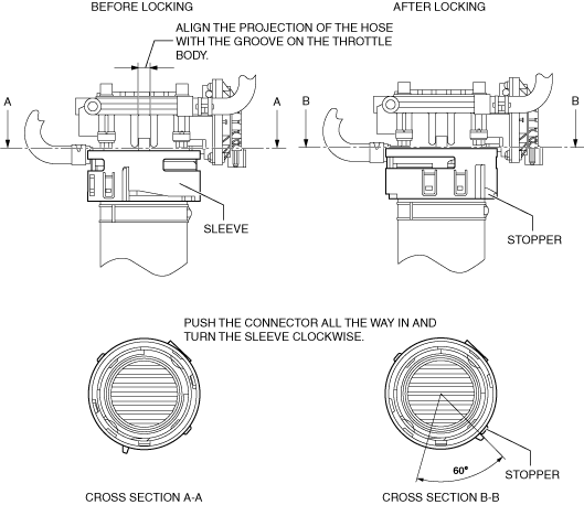
Charge Air Cooler Outlet Hose Installation Note
1. Install the charge air cooler outlet hose as shown in the figure.
ac5uuw00010797
|
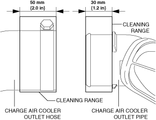
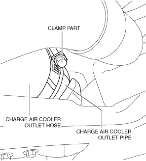
Hose Clamp Installation Note
1. Visually inspect the charge air cooler outlet hose and charge air cooler outlet pipe.
2. Use a clean cloth to clean the outer surfaces of the charge air cooler outlet pipe and the inner surface of the charge air cooler outlet hose.
ac5wzw00007964
|
3. Temporarily install a new hose clamp to the charge air cooler outlet hose. (Do not tighten hose clamp)
ac5wzw00007965
|
4. Insert the charge air cooler outlet hose until it contacts the charge air cooler outlet pipe stopper.
ac5wzw00007966
|
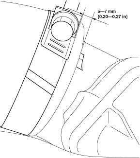
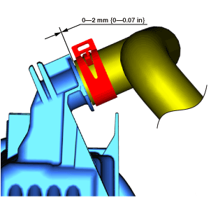
5. Re-position the temporarily installed hose clamp to the position 5—7 mm {0.20—0.27 in} from the charge air cooler outlet pipe stopper.
ac5wzw00007967
|
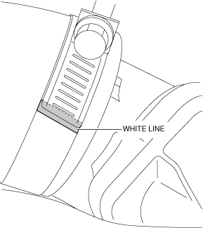
6. Tighten the hose clamp until the clamp end rides on top of the white line.
ac5wzw00007968
|
7. Install the front under cover No.1 and the front under cover No.2. (See FRONT UNDER COVER No.1 REMOVAL/INSTALLATION.) (See FRONT UNDER COVER No.2 REMOVAL/INSTALLATION.)
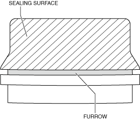
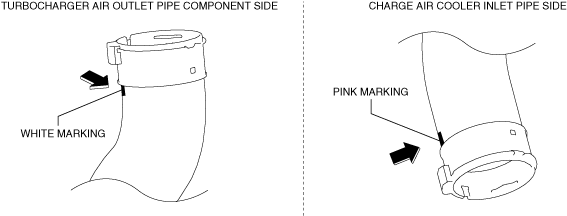
Charge Air Cooler Inlet Hose Installation Note
1. Clean the seal surface and furrow area of the charge air cooler air inlet pipe and turbocharger air outlet pipe component.
ac5wzw00006724
|
2. Degrease the seal surface of the pipe, and verify if there is foreign matter penetration or scratches.
3. Apply engine oil to the seal surface of the pipe.
ac5wzw00006725
|
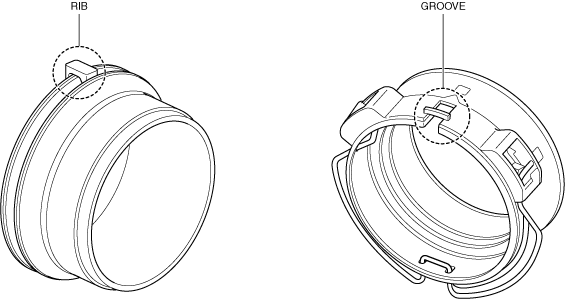
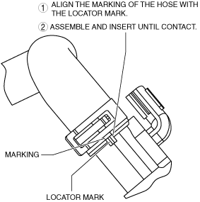
4. Align the pipe rib and connector groove positions, and install.
ac5wzw00006726
|
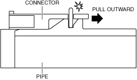
5. Insert the pipe connector completely into the connector.
ac5wzw00006727
|
6. Pull the pipe outward and verify that a click sound is heard.
ac5wzw00006728
|
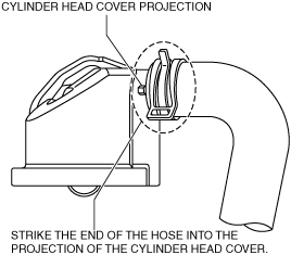
Breather Hose Installation Note (Fuel injector (2pin type))
1. Install the breather hose as shown in the figure.
Cylinder head cover side
ac5wzw00005686
|
Blow-by heater side
ac5wzw00005687
|
Breather Hose Installation Note (Fuel injector (6pin type))
1. Install the breather hose as shown in the figure.
Cylinder head cover side
ac5wzw00012063
|
Blow-by heater side
ac5wzw00012064
|
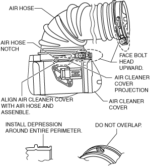
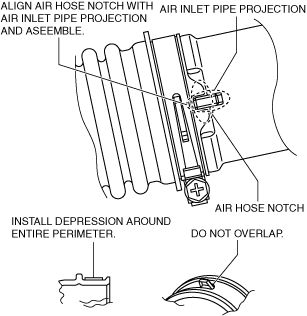
Air Hose Installation Note
1. Install the air hose as shown in the figure.
Air cleaner cover side
ac5wzw00005688
|
Air inlet pipe side
ac5wzw00005689
|
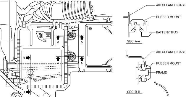
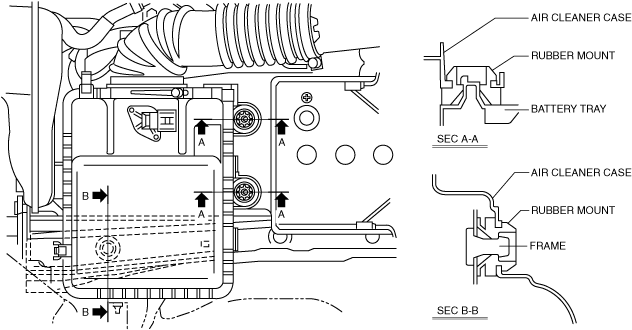
Air Cleaner case installation note
1. Install the air cleaner case as shown in the figure.
Fuel injector (2pin type)
ac5wzw00005690
|
Fuel injector (6pin type)
ac5wzw00012065
|
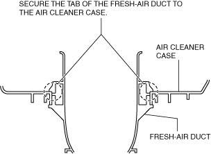
Fresh-air Duct Installation Note
1. Install the fresh-air duct as shown in the figure.
ac5wzw00005691
|
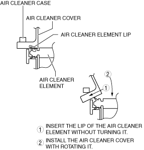
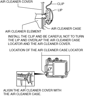
Air Cleaner Cover Installation Note
1. Install the air cleaner cover as shown in the figure.
ac5wzw00005692
|
2. Secure the air cleaner cover and the air cleaner case with the clip.
ac5wzw00005693
|
Vacuum Hose Installation Note
1. Install the vacuum hose as shown in the figure.
ac5wzw00005694
|