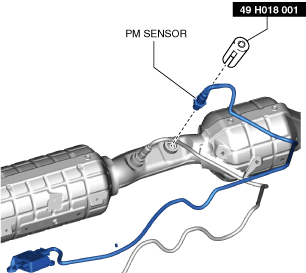
49 H018 001
Wrench

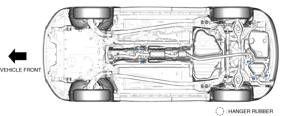
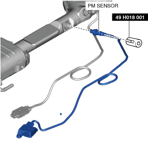
PM SENSOR REMOVAL/INSTALLATION [SKYACTIV-D 2.2]
id0140z7825900
Special Service Tool (SST)
|
49 H018 001
Wrench
|
|
Replacement Part
|
Band
Quantity: 7
Location of use: PM sensor (2WD)
|
Band
Quantity: 5
Location of use: PM sensor (4WD)
|
2WD
Removal
1. Disconnect the negative battery terminal. (See NEGATIVE BATTERY TERMINAL DISCONNECTION/CONNECTION.)
2. Remove the following parts:
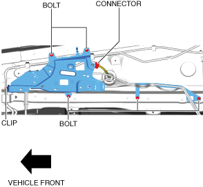
3. Remove the clip.
ac5uuw00008661
|
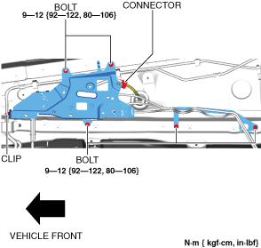
4. Remove the bolts.
5. Disconnect the connector.
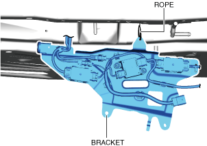
6. Suspend module bracket using a rope as shown in the figure.
ac5uuw00008662
|
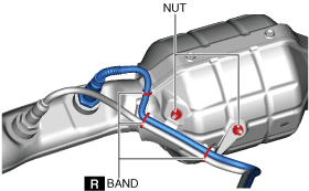
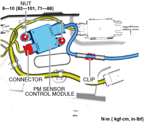
7. Remove the nuts.
ac5uuw00008663
|
8. Disconnect the connector.
9. Remove the clip.
10. Remove the PM sensor control module.
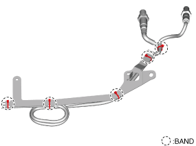
11. Cut the bands.
ac5uuw00008664
|
12. Remove the nuts, and remove the bracket from the SCR converter.
ac5uuw00008665
|
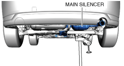
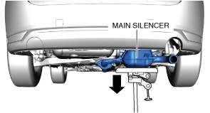
13. Cut the bands.
14. Support the main silencer using a transmission jack.
ac5uuw00008666
|
15. Remove the hanger rubber.
ac5uuw00008667
|
16. Lower the transmission jack slowly to a position allowing removal of the PM sensor.
ac5uuw00008668
|
17. Remove the PM sensor using the SST.
ac5uuw00008669
|
Installation
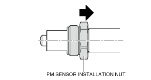
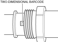
1. Slide the PM sensor installation nut in the direction shown in the figure.
ac5wzw00014319
|
2. Verify the two-dimensional barcode.
ac5wzw00014320
|
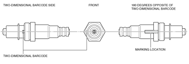
3. Mark the PM sensor at the position 180 degrees opposite of the two-dimensional barcode as shown in the figure.
ac5wzw00014321
|
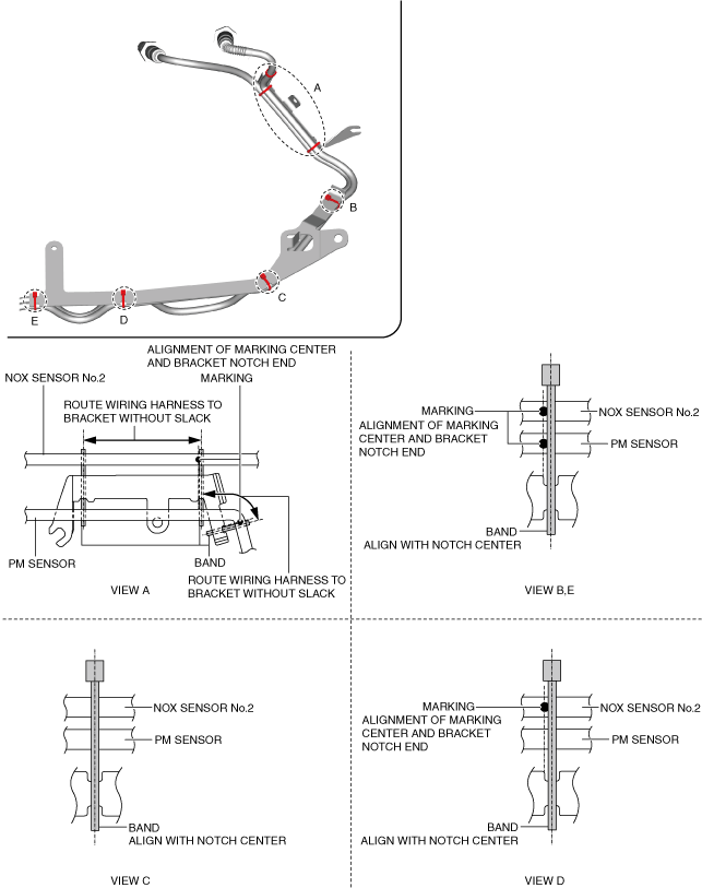
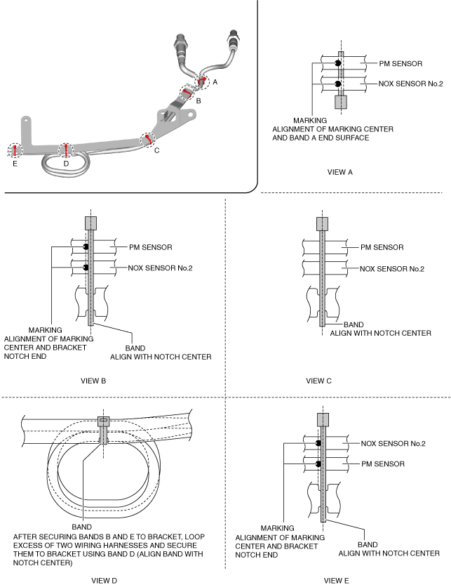
4. Install the bands. (seeBand installation note.)
ac5uuw00008670
|
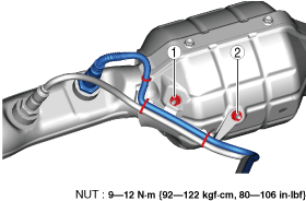
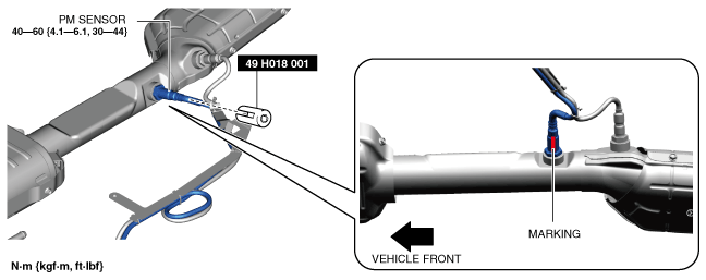
5. Tighten the nuts in the order shown in the figure.
ac5uuw00008671
|
6. Using the SST, assemble the PM sensor so that the marking placed in Step 3 is facing the ground.
ac5wzw00014322
|
7. Verify the direction the PM sensor marking is facing.
8. Lift up the transmission jack slowly to a position allowing installation of the hanger rubber.
ac5uuw00008682
|
9. Install the hanger rubber.
ac5uuw00008667
|
10. Install the clip.
ac5uuw00008674
|
11. Connect the connector.
12. Install the PM sensor control module.
13. Install the nuts.
14. Connect the connector.
ac5uuw00008675
|
15. Install the bolts.
16. Install the clip.
17. Install the following parts:
18. Connect the negative battery terminal. (See NEGATIVE BATTERY TERMINAL DISCONNECTION/CONNECTION.)
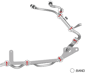
Band installation note
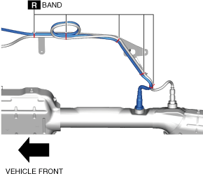
1. Install bands as shown in the figure.
ac5uuw00008676
|
4WD
Removal
1. Disconnect the negative battery terminal. (See NEGATIVE BATTERY TERMINAL DISCONNECTION/CONNECTION.)
2. Remove the floor under cover (LH). (See FLOOR UNDER COVER REMOVAL/INSTALLATION.)
3. Remove the clip.
ac5uuw00008661
|
4. Remove the bolts.
5. Disconnect the connector.
6. Suspend module bracket using a rope as shown in the figure.
ac5uuw00008662
|
7. Remove the nuts.
ac5uuw00008663
|
8. Disconnect the connector.
9. Remove the clip.
10. Remove the PM sensor control module.
11. Cut the bands.
ac5uuw00008677
|
12. Remove the PM sensor using the SST.
ac5uuw00008678
|
Installation
1. Slide the PM sensor installation nut in the direction shown in the figure.
ac5wzw00014319
|
2. Verify the two-dimensional barcode.
ac5wzw00014320
|
3. Mark the PM sensor at the position 180 degrees opposite of the two-dimensional barcode as shown in the figure.
ac5wzw00014321
|
4. Install the bands. (seeBand installation note.)
ac5uuw00008679
|
5. Using the SST, assemble the PM sensor so that the marking placed in Step 3 is facing the ground.
ac5wzw00014323
|
6. Verify the direction the PM sensor marking is facing.
7. Install the clip.
ac5uuw00008674
|
8. Connect the connector.
9. Install the PM sensor control module.
10. Install the nuts.
11. Connect the connector.
ac5uuw00008675
|
12. Install the bolts.
13. Install the clip.
14. Install the floor under cover (LH). (See FLOOR UNDER COVER REMOVAL/INSTALLATION.)
15. Connect the negative battery terminal. (See NEGATIVE BATTERY TERMINAL DISCONNECTION/CONNECTION.)
Band installation note
1. Install bands as shown in the figure.
ac5uuw00008681
|