 |
ac5wzw00005796
EXHAUST SYSTEM REMOVAL/INSTALLATION [SKYACTIV-D 2.2]
id0115z7800200
Replacement Part (Fuel injector (2pin type))
|
Gasket
Quantity: 1
Location of use: Main silencer
|
Nut
Quantity: 4
Location of use: Middle pipe
|
Gasket
Quantity: 1
Location of use: Middle pipe
|
|
Gasket
Quantity: 3
Location of use: Catalytic converter
|
Washer
Quantity: 1
Location of use: Catalytic converter
|
Exhaust gas pressure hose
Quantity: 2
Location of use: Catalytic converter
|
|
Clip
Quantity: 2
Location of use: Catalytic converter
|
—
|
—
|
Replacement Part (Fuel injector (6pin type))
|
Gasket
Quantity: 1
Location of use: Main silencer
|
Nut
Quantity: 4
Location of use: Middle pipe
|
Gasket
Quantity: 1
Location of use: Middle pipe
|
|
Gasket
Quantity: 3
Location of use: Catalytic converter
|
Washer
Quantity: 2
Location of use: Catalytic converter
|
Gasket
Quantity: 1
Location of use: Exhaust manifold
|
|
Nut
Quantity: 10
Location of use: Exhaust manifold
|
Stud
Quantity: 10
Location of use: Exhaust manifold
|
Exhaust gas pressure hose
Quantity: 2
Location of use: Catalytic converter
|
|
Clip
Quantity: 2
Location of use: Catalytic converter
|
—
|
—
|
Operation After Replacing Catalytic Converter
1. If the catalytic converter is replaced, perform the following procedure.
|
STEP |
ACTION |
PAGE/CONDITION |
|---|---|---|
|
1
|
Perform diesel particulate filter data reset procedure.
|
|
|
2
|
Switch the ignition off.
|
—
|
|
3
|
Wait for 20 s. (Fuel injector (2pin type))
Wait for 30 s. (Fuel injector (6pin type))
|
—
|
|
4
|
Switch the ignition ON (engine off).
|
—
|
|
5
|
Perform KOEO self-test procedure.
|
|
|
6
|
Perform KOER self-test procedure.
|
|
|
7
|
Perform fuel injector injection amount correction.
|
|
|
8
|
Perform compulsory diesel particulate filter regeneration.
|
|
|
9
|
Clear the DTCs.
|
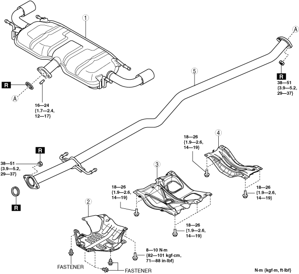
Exhaust System Removal/Installation (2WD) (Fuel injector (2pin type))
1. Disconnect the negative battery terminal. (See NEGATIVE BATTERY TERMINAL DISCONNECTION/CONNECTION.)
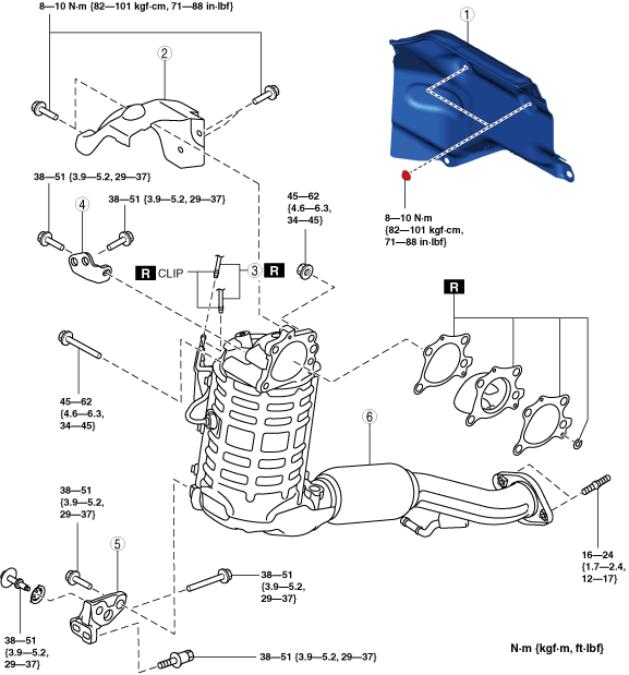
2. Remove in the order shown in the figure.
3. Remove the exhaust system insulator. (See Exhaust system insulator removal/installation (2WD) (Fuel injector (2pin type)).)
4. Install in the reverse order of removal.
Step 1
ac5wzw00005796
|
|
1
|
Main silencer
|
|
2
|
Plate
|
|
3
|
Brace bar
|
|
4
|
Tunnel member
|
|
5
|
Middle pipe
|
Step 2
ac5wzw00014360
|
|
1
|
Insulator
|
|
2
|
Catalytic converter insulator
|
|
3
|
Exhaust gas pressure hose
|
|
4
|
Catalytic converter upper bracket
|
|
5
|
Catalytic converter lower bracket
|
|
6
|
Catalytic converter
|
Exhaust system insulator removal/installation (2WD) (Fuel injector (2pin type))
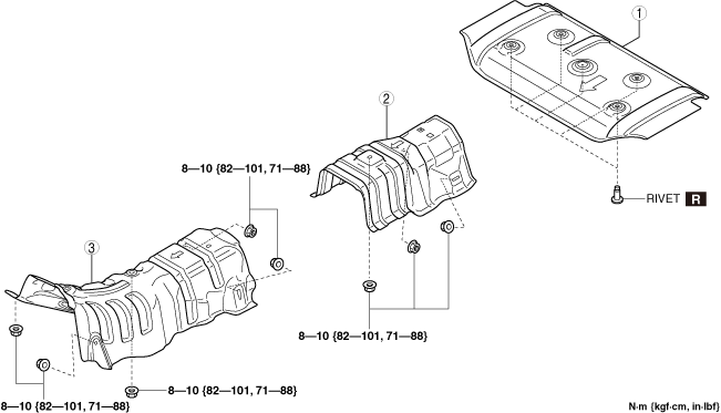
1. Remove in the order shown in the figure.
2. Install in the reverse order of removal.
ac5wzw00013596
|
|
1
|
Insulator (rear)
|
|
2
|
Insulator (middle)
|
|
3
|
Insulator (front)
|
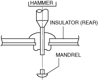
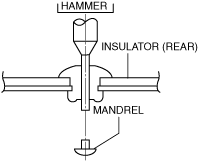
Insulator (rear) removal note (2WD) (Fuel injector (2pin type))
1. Using a hammer and punch (diam. 2—2.8 mm{0.08—0.11 in}), punch out the mandrel.
ac5wzw00005799
|
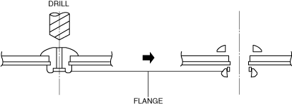
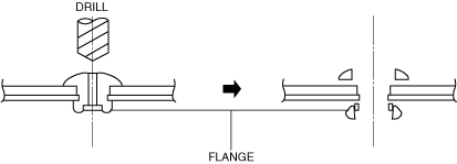
2. Pull out and remove the flange using a drill (diam. 5 mm{0.2 in}).
ac5wzw00005800
|
Brace bar removal note (2WD) (Fuel injector (2pin type))
1. Remove the floor and cover. (See FLOOR UNDER COVER REMOVAL/INSTALLATION.)
2. Remove the brace bar.
Insulator removal note (2WD) (Fuel injector (2pin type))
1. Remove the windshield wiper arm and blade. (See WINDSHIELD WIPER ARM AND BLADE REMOVAL/INSTALLATION.)
2. Remove the cowl grille (See COWL GRILLE REMOVAL/INSTALLATION.).
3. Remove the windshield wiper motor and link. (See WINDSHIELD WIPER MOTOR AND LINK REMOVAL/INSTALLATION.)
4. Remove the cowl panel. (See COWL PANEL REMOVAL/INSTALLATION.)
5. Remove the insulator.
Catalytic converter lower bracket removal note (2WD) (Fuel injector (2pin type))
1. Remove the front crossmember. (See FRONT CROSSMEMBER REMOVAL/INSTALLATION.)
2. Remove the catalytic converter lower bracket.
Catalytic converter removal note (2WD) (Fuel injector (2pin type))
1. Disconnect the exhaust gas temperature sensor No.2 connector.
2. Disconnect the exhaust gas temperature sensor No.3 connector.
3. Remove the exhaust gas temperature sensor No.3 wiring harness installation nuts. (See EXHAUST GAS TEMPERATURE SENSOR REMOVAL/INSTALLATION [SKYACTIV-D 2.2].)
4. Disconnect the A/F sensor connector.
5. Remove the catalytic converter.
Catalytic converter installation note (2WD) (Fuel injector (2pin type))
1. Temporarily tighten bolt and nuts shown in the figure.
ac5wzw00005801
|
2. Tighten the bolt and nuts in the other shown in the figure.
ac5wzw00005802
|
3. After installation, verify that the tightening torque for the bolt and nuts is correct.
Catalytic converter bracket installation note (2WD) (Fuel injector (2pin type))
1. Temporarily tighten bolts 1 and bolt 2 shown in the figure.
ac5wzw00005803
|
2. Tighten bolts 1 shown in the figure.
3. Tighten bolts 2 shown in the figure.
4. All the conclusions check after attachment whether it is the right torque.
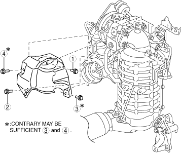
5. Temporarily tighten bolts 3 and bolt 4 shown in the figure.
ac5wzw00005804
|
6. Tighten the bolts in the order shown in the figure.
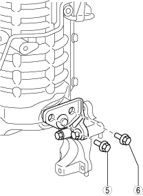
7. Temporarily tighten bolts 5 and bolt 6 shown in the figure.
ac5wzw00005805
|
8. Tighten the bolts in the order shown in the figure.
9. All the conclusions check after attachment whether it is the right torque.
Catalytic converter insulator installation note (2WD) (Fuel injector (2pin type))
1. Temporarily tighten the catalytic converter insulator installation bolts.
2. Tighten the bolts in the order shown in the figure.
ac5wzw00005806
|
Exhaust System Removal/Installation (4WD) (Fuel injector (2pin type))
1. Disconnect the negative battery terminal. (See NEGATIVE BATTERY TERMINAL DISCONNECTION/CONNECTION.)
2. Remove in the order shown in the figure.
3. Remove the exhaust system insulator. (See Exhaust system insulator removal/installation (4WD) (Fuel injector (2pin type)).)
4. Install in the reverse order of removal.
Step 1
ac5wzw00005807
|
|
1
|
Main silencer
|
|
2
|
Middle pipe
|
Step 2
ac5wzw00014361
|
|
1
|
Insulator
|
|
2
|
Catalytic converter insulator
|
|
3
|
Exhaust gas pressure hose
|
|
4
|
Catalytic converter upper bracket
|
|
5
|
Catalytic converter lower bracket
|
|
6
|
Catalytic converter
|
Exhaust system insulator removal/installation (4WD) (Fuel injector (2pin type))
1. Remove the propeller shaft. (See PROPELLER SHAFT REMOVAL/INSTALLATION.)
2. Remove in the order shown in the figure.
3. Install in the reverse order of removal.
ac5wzw00013596
|
|
1
|
Insulator (rear)
|
|
2
|
Insulator (middle)
|
|
3
|
Insulator (front)
|
Insulator (rear) removal note (4WD) (Fuel injector (2pin type))
1. Using a hammer and punch (diam. 2—2.8 mm {0.08—0.11}), punch out the mandrel.
ac5wzw00005810
|
2. Pull out and remove the flange using a drill (diam. 5 mm {0.2 in})
ac5wzw00005811
|
Insulator removal note (4WD) (Fuel injector (2pin type))
1. Remove the windshield wiper arm and blade. (See WINDSHIELD WIPER ARM AND BLADE REMOVAL/INSTALLATION.)
2. Remove the cowl grille (See COWL GRILLE REMOVAL/INSTALLATION.).
3. Disconnect the windshield wiper de-icer connector. (See WINDSHIELD REMOVAL.)(See WINDSHIELD INSTALLATION.)
4. Remove the windshield wiper motor and link. (See WINDSHIELD WIPER MOTOR AND LINK REMOVAL/INSTALLATION.)
5. Remove the cowl panel. (See COWL PANEL REMOVAL/INSTALLATION.)
6. Remove the insulator.
Catalytic converter lower bracket removal note (4WD) (Fuel injector (2pin type))
1. Remove the front crossmember. (See FRONT CROSSMEMBER REMOVAL/INSTALLATION.)
2. Remove the catalytic converter lower bracket.
Catalytic converter removal note (4WD) (Fuel injector (2pin type))
1. Disconnect the exhaust temperature sensor No.2 connector.
2. Disconnect the exhaust temperature sensor No.3 connector.
3. Remove the exhaust temperature sensor No.3 wiring harness bracket installation nuts. (See EXHAUST GAS TEMPERATURE SENSOR REMOVAL/INSTALLATION [SKYACTIV-D 2.2].)
4. Disconnect the A/F sensor connector.
5. Remove the catalytic converter.
Catalytic converter installation note (4WD) (Fuel injector (2pin type))
1. Temporarily tighten bolt and nuts shown in the figure.
ac5wzw00005801
|
2. Tighten the bolt and nuts in the other shown in the figure.
ac5wzw00005802
|
3. After installation, verify that the tightening torque for the bolt and nuts is correct.
Catalytic converter bracket installation note (4WD) (Fuel injector (2pin type))
1. Temporarily tighten bolts 1 and bolt 2 shown in the figure.
ac5wzw00005803
|
2. Tighten bolts 1 shown in the figure.
3. Tighten bolts 2 shown in the figure.
4. All the conclusions check after attachment whether it is the right torque.
5. Temporarily tighten bolts 3 and bolt 4 shown in the figure.
ac5wzw00005804
|
6. Tighten the bolts in the order shown in the figure.
7. Temporarily tighten bolts 5 and bolt 6 shown in the figure.
ac5wzw00005805
|
8. Tighten the bolts in the order shown in the figure.
9. All the conclusions check after attachment whether it is the right torque.
Catalytic converter insulator installation note (4WD) (Fuel injector (2pin type))
1. Temporarily tighten the catalytic converter insulator installation bolts.
2. Tighten the bolts in the order shown in the figure.
ac5wzw00005806
|
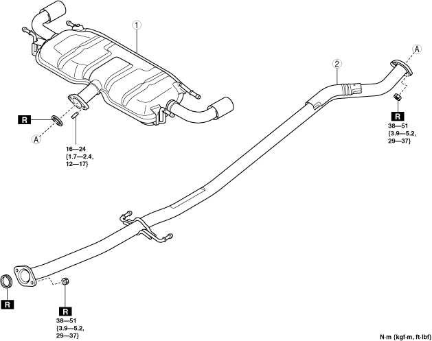
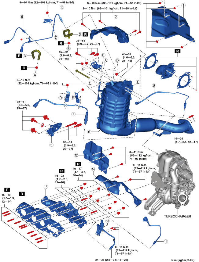
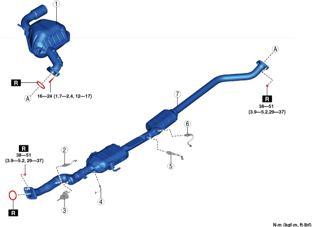
Exhaust System Removal/Installation (2WD) (Fuel injector (6pin type))
1. Disconnect the negative battery terminal. (See NEGATIVE BATTERY TERMINAL DISCONNECTION/CONNECTION.)
2. Remove in the order shown in the figure.
3. Remove the exhaust system insulator. (See Exhaust system insulator removal/installation (2WD) (Fuel injector (6pin type)).)
4. Install in the reverse order of removal.
Step 1 (Without SCR system)
ac5wzw00005796
|
|
1
|
Main silencer
|
|
2
|
Plate
|
|
3
|
Brace bar
|
|
4
|
Tunnel member
|
|
5
|
Middle pipe
|
Step 1 (With SCR system)
ac5uuw00008634
|
|
1
|
Main silencer
|
|
2
|
Insulator
|
|
3
|
Brace bar
|
|
4
|
Tunnel member
|
|
5
|
NOx sensor No.1
|
|
6
|
Urea injector
|
|
7
|
Exhaust gas temperature sensor No.5
|
|
8
|
NOx sensor No.2
|
|
9
|
PM sensor
|
|
10
|
SCR converter
|
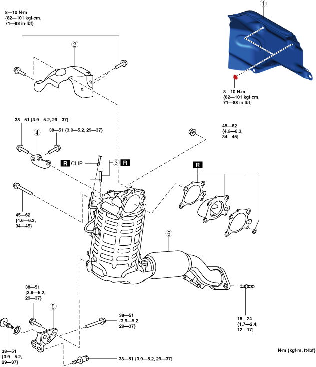
Step 2
ac5wzw00014362
|
|
1
|
Insulator
|
|
2
|
Catalytic converter insulator
|
|
3
|
Exhaust gas pressure hose
|
|
4
|
Catalytic converter upper bracket
|
|
5
|
Catalytic converter lower bracket
|
|
6
|
Catalytic converter
|
|
7
|
A/F sensor
|
|
8
|
Exhaust gas temperature sensor No.4 (With SCR system)
|
|
9
|
Exhaust gas temperature sensor No.3
|
|
10
|
Exhaust gas temperature sensor No.2
|
|
11
|
Exhaust gas temperature sensor No.1
|
|
12
|
Insulator
|
|
13
|
Exhaust gas pressure sensor No.1 component
|
|
14
|
Exhaust manifold insulator
|
|
15
|
Exhaust manifold
|
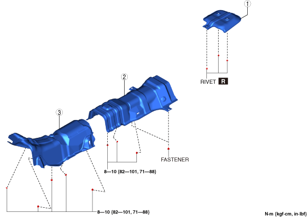
Exhaust system insulator removal/installation (2WD) (Fuel injector (6pin type))
1. Remove in the order shown in the figure.
2. Install in the reverse order of removal.
Without SCR system
ac5wzw00013596
|
|
1
|
Insulator (rear)
|
|
2
|
Insulator (middle)
|
|
3
|
Insulator (front)
|
With SCR system
ac5wzw00013597
|
|
1
|
Insulator (rear)
|
|
2
|
Insulator (middle)
|
|
3
|
Insulator (front)
|
Insulator (rear) removal note (2WD) (Fuel injector (6pin type))
1. Using a hammer and punch (diam. 2—2.8 mm{0.08—0.11 in}), punch out the mandrel.
ac5wzw00005799
|
2. Pull out and remove the flange using a drill (diam. 5 mm{0.2 in}).
ac5wzw00005800
|
Brace bar removal note (2WD) (Fuel injector (6pin type))
1. Remove the floor and cover. (See FLOOR UNDER COVER REMOVAL/INSTALLATION.)
2. Remove the brace bar.
Insulator removal note (2WD) (Fuel injector (6pin type))
1. Remove the windshield wiper arm and blade. (See WINDSHIELD WIPER ARM AND BLADE REMOVAL/INSTALLATION.)
2. Remove the cowl grille (See COWL GRILLE REMOVAL/INSTALLATION.).
3. Remove the windshield wiper motor and link. (See WINDSHIELD WIPER MOTOR AND LINK REMOVAL/INSTALLATION.)
4. Remove the cowl panel. (See COWL PANEL REMOVAL/INSTALLATION.)
5. Remove the insulator.
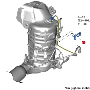
Catalytic converter insulator removal note (2WD) (Fuel injector (6pin type))
1. Disconnect the exhaust gas temperature sensor No.2 connector. (See EXHAUST GAS TEMPERATURE SENSOR REMOVAL/INSTALLATION [SKYACTIV-D 2.2].)
2. Remove the nut shown in the figure. (See EXHAUST GAS TEMPERATURE SENSOR REMOVAL/INSTALLATION [SKYACTIV-D 2.2].)
ac5wzw00012207
|
3. Remove the wiring harness clip shown in the figure.
ac5wzw00012208
|
4. Remove the catalytic converter insulator.
Catalytic converter lower bracket removal note (2WD) (Fuel injector (6pin type))
1. Remove the front crossmember. (See FRONT CROSSMEMBER REMOVAL/INSTALLATION.)
2. Remove the catalytic converter lower bracket.
Catalytic converter removal note (2WD) (Fuel injector (6pin type))
1. Disconnect the exhaust gas temperature sensor No.3 connector.
2. Disconnect the exhaust gas temperature sensor No.4 connector. (With SCR system)
3. Disconnect the A/F sensor connector.
4. Remove the catalytic converter.
Exhaust manifold removal note (2WD) (Fuel injector (6pin type))
1. Remove the turbocharger. (See TURBOCHARGER REMOVAL/INSTALLATION [SKYACTIV-D 2.2].)
2. Set the exhaust gas temperature sensor No.1 out of the way. (See EXHAUST GAS TEMPERATURE SENSOR REMOVAL/INSTALLATION [SKYACTIV-D 2.2].)
3. Remove the exhaust gas pressure sensor No.1 component.
4. Remove the exhaust manifold insulator.
5. Remove the exhaust manifold.
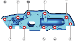
Exhaust manifold installation note (2WD) (Fuel injector (6pin type))
1. Install the new studs to the cylinder head.
2. Tighten the nuts in the other shown in the figure.
ac5wzw00012209
|
3. Tighten the nuts in the other shown in the figure.
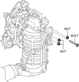
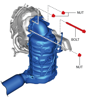
Catalytic converter installation note (2WD) (Fuel injector (6pin type))
1. Temporarily tighten bolt and nuts shown in the figure.
ac5wzw00012210
|
2. Tighten the bolt and nuts in the other shown in the figure.
ac8jjw00002109
|
3. After installation, verify that the tightening torque for the bolt and nuts is correct.
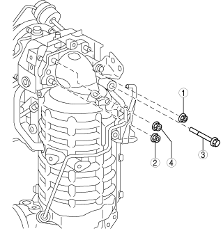
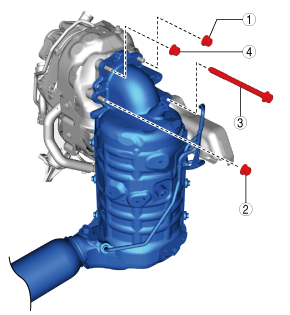
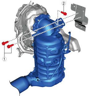
Catalytic converter bracket installation note (2WD) (Fuel injector (6pin type))
1. Temporarily tighten bolts 1 and bolt 2 shown in the figure.
ac8jjw00002110
|
2. Tighten bolts 1 shown in the figure.
3. Tighten bolts 2 shown in the figure.
4. All the conclusions check after attachment whether it is the right torque.
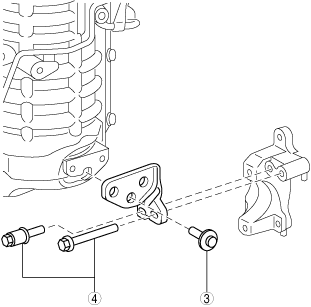
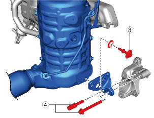
5. Temporarily tighten bolts 3 and bolt 4 shown in the figure.
ac8jjw00002111
|
6. Tighten the bolts in the order shown in the figure.
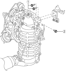
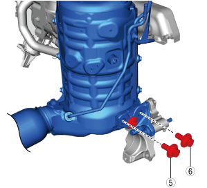
7. Temporarily tighten bolts 5 and bolt 6 shown in the figure.
ac8jjw00002112
|
8. Tighten the bolts in the order shown in the figure.
9. All the conclusions check after attachment whether it is the right torque.
Catalytic converter insulator installation note (2WD) (Fuel injector (6pin type))
1. Temporarily tighten the catalytic converter insulator installation bolts.
2. Tighten the bolts in the order shown in the figure.
ac8jjw00002113
|
Exhaust System Removal/Installation (4WD) (Fuel injector (6pin type))
1. Disconnect the negative battery terminal. (See NEGATIVE BATTERY TERMINAL DISCONNECTION/CONNECTION.)
2. Remove in the order shown in the figure.
3. Remove the exhaust system insulator. (See Exhaust system insulator removal/installation (4WD) (Fuel injector (6pin type)).)
4. Install in the reverse order of removal.
Step 1 (Without SCR system)
ac5wzw00005807
|
|
1
|
Main silencer
|
|
2
|
Middle pipe
|
Step 1 (With SCR system)
ac5uuw00008643
|
|
1
|
Main silencer
|
|
2
|
NOx sensor No.1
Exhaust gas temperature sensor No.5
|
|
3
|
Urea injector
|
|
4
|
Exhaust gas temperature sensor No.5
|
|
5
|
NOx sensor No.2
|
|
6
|
PM sensor
|
|
7
|
SCR converter
|
Step 2
ac5wzw00014362
|
|
1
|
Insulator
|
|
2
|
Catalytic converter insulator
|
|
3
|
Exhaust gas pressure hose
|
|
4
|
Catalytic converter upper bracket
|
|
5
|
Catalytic converter lower bracket
|
|
6
|
Catalytic converter
|
|
7
|
A/F sensor
|
|
8
|
Exhaust gas temperature sensor No.4 (With SCR system)
|
|
9
|
Exhaust gas temperature sensor No.3
|
|
10
|
Exhaust gas temperature sensor No.2
|
|
11
|
Exhaust gas temperature sensor No.1
|
|
12
|
Insulator
|
|
13
|
Exhaust gas pressure sensor No.1 component
|
|
14
|
Exhaust manifold insulator
|
|
15
|
Exhaust manifold
|
Exhaust system insulator removal/installation (4WD) (Fuel injector (6pin type))
1. Remove the propeller shaft. (See PROPELLER SHAFT REMOVAL/INSTALLATION.)
2. Remove in the order shown in the figure.
3. Install in the reverse order of removal.
Without SCR system
ac5wzw00013596
|
|
1
|
Insulator (rear)
|
|
2
|
Insulator (middle)
|
|
3
|
Insulator (front)
|
With SCR system
ac5wzw00013597
|
|
1
|
Insulator (rear)
|
|
2
|
Insulator (middle)
|
|
3
|
Insulator (front)
|
Insulator (rear) removal note (4WD) (Fuel injector (6pin type))
1. Using a hammer and punch (diam. 2—2.8 mm {0.08—0.11}), punch out the mandrel.
ac5wzw00005810
|
2. Pull out and remove the flange using a drill (diam. 5 mm {0.2 in})
ac5wzw00005811
|
Insulator removal note (4WD) (Fuel injector (6pin type))
1. Remove the windshield wiper arm and blade. (See WINDSHIELD WIPER ARM AND BLADE REMOVAL/INSTALLATION.)
2. Remove the cowl grille (See COWL GRILLE REMOVAL/INSTALLATION.).
3. Disconnect the windshield wiper de-icer connector. (See WINDSHIELD REMOVAL.)(See WINDSHIELD INSTALLATION.)
4. Remove the windshield wiper motor and link. (See WINDSHIELD WIPER MOTOR AND LINK REMOVAL/INSTALLATION.)
5. Remove the cowl panel. (See COWL PANEL REMOVAL/INSTALLATION.)
6. Remove the insulator.
Catalytic converter insulator removal note (4WD) (Fuel injector (6pin type))
1. Disconnect the exhaust gas temperature sensor No.2 connector. (See EXHAUST GAS TEMPERATURE SENSOR REMOVAL/INSTALLATION [SKYACTIV-D 2.2].)
2. Remove the nut shown in the figure. (See EXHAUST GAS TEMPERATURE SENSOR REMOVAL/INSTALLATION [SKYACTIV-D 2.2].)
ac5wzw00012207
|
3. Remove the wiring harness clip shown in the figure.
ac5wzw00012208
|
4. Remove the catalytic converter insulator.
Catalytic converter lower bracket removal note (4WD) (Fuel injector (6pin type))
1. Remove the front crossmember. (See FRONT CROSSMEMBER REMOVAL/INSTALLATION.)
2. Remove the catalytic converter lower bracket.
Catalytic converter removal note (4WD) (Fuel injector (6pin type))
1. Disconnect the exhaust temperature sensor No.3 connector.
2. Disconnect the exhaust gas temperature sensor No.4 connector. (With SCR system)
3. Disconnect the A/F sensor connector.
4. Remove the catalytic converter.
Exhaust manifold removal note (4WD) (Fuel injector (6pin type))
1. Remove the turbocharger. (See TURBOCHARGER REMOVAL/INSTALLATION [SKYACTIV-D 2.2].)
2. Set the exhaust gas temperature sensor No.1 out of the way. (See EXHAUST GAS TEMPERATURE SENSOR REMOVAL/INSTALLATION [SKYACTIV-D 2.2].)
3. Remove the exhaust gas pressure sensor No.1 component.
4. Remove the exhaust manifold insulator.
5. Remove the exhaust manifold.
Exhaust manifold installation note (4WD) (Fuel injector (6pin type))
1. Install the new studs to the cylinder head.
2. Tighten the nuts in the other shown in the figure.
ac5wzw00012209
|
3. Tighten the nuts in the other shown in the figure.
Catalytic converter installation note (4WD) (Fuel injector (6pin type))
1. Temporarily tighten bolt and nuts shown in the figure.
ac5wzw00012210
|
2. Tighten the bolt and nuts in the other shown in the figure.
ac8jjw00002109
|
3. After installation, verify that the tightening torque for the bolt and nuts is correct.
Catalytic converter bracket installation note (4WD) (Fuel injector (6pin type))
1. Temporarily tighten bolts 1 and bolt 2 shown in the figure.
ac8jjw00002110
|
2. Tighten bolts 1 shown in the figure.
3. Tighten bolts 2 shown in the figure.
4. All the conclusions check after attachment whether it is the right torque.
5. Temporarily tighten bolts 3 and bolt 4 shown in the figure.
ac8jjw00002111
|
6. Tighten the bolts in the order shown in the figure.
7. Temporarily tighten bolts 5 and bolt 6 shown in the figure.
ac8jjw00002112
|
8. Tighten the bolts in the order shown in the figure.
9. All the conclusions check after attachment whether it is the right torque.
Catalytic converter insulator installation note (4WD) (Fuel injector (6pin type))
1. Temporarily tighten the catalytic converter insulator installation bolts.
2. Tighten the bolts in the order shown in the figure.
ac8jjw00002113
|