 |
ac5uuw00006536
REAR STABILIZER REMOVAL/INSTALLATION [2WD]
id0214008005a1
1. Switch the ignition ON (engine off).
2. Release the electric parking brake.
3. Switch the ignition off.
4. Disconnect the negative battery terminal. (See NEGATIVE BATTERY TERMINAL DISCONNECTION/CONNECTION.)
5. Remove the wheels and tires. (See WHEEL AND TIRE REMOVAL/INSTALLATION.)
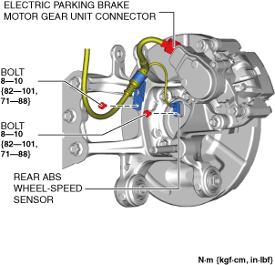
6. Disconnect the rear ABS wheel-speed sensor wiring harness and the electric parking brake motor gear unit connector and set it aside so that it does not interfere with the servicing. (See REAR ABS WHEEL-SPEED SENSOR REMOVAL/INSTALLATION [2WD].)
ac5uuw00006536
|
7. Remove the following parts:
8. Remove the following parts: (See EXHAUST SYSTEM REMOVAL/INSTALLATION [WITHOUT CYLINDER DEACTIVATION (SKYACTIV-G 2.0, SKYACTIV-G 2.5)].) (See EXHAUST SYSTEM REMOVAL/INSTALLATION [WITH CYLINDER DEACTIVATION (SKYACTIV-G 2.0, SKYACTIV-G 2.5)].) (See EXHAUST SYSTEM REMOVAL/INSTALLATION [SKYACTIV-D 2.2].)
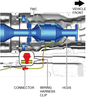
9. For SKYACTIV-G (Without cylinder deactivation) vehicles, perform the following procedure:
ac5uuw00006565
|
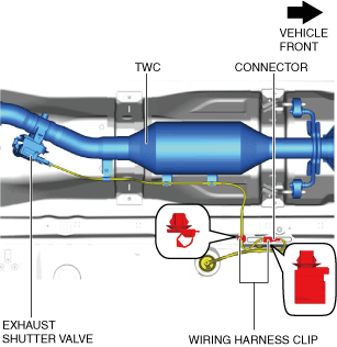
10. For SKYACTIV-G (With cylinder deactivation) vehicles, perform the following procedure:
ac5uuw00009354
|
ac5uuw00009355
|
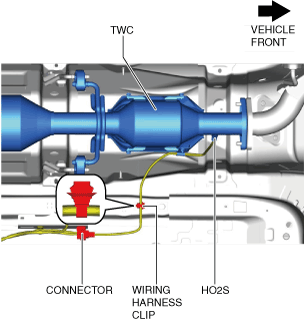
11. For SKYACTIV-D 2.2 (Without SCR system) vehicles, perform the following procedure:
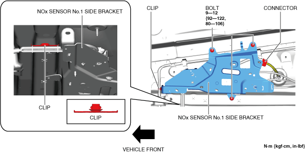
12. For SKYACTIV-D 2.2 (With SCR system) vehicles, perform the following procedure:
ac5uuw00009041
|
ac5uuw00009042
|
13. Remove the rear coil spring. (See REAR COIL SPRING REMOVAL/INSTALLATION.)
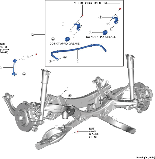
14. Remove in the order indicated in the table.
15. Install in the reverse order of removal. (See Suspension Links Installation Note.)
16. Inspect the wheel alignment and adjust it if necessary. (See REAR WHEEL ALIGNMENT.)
ac5uuw00006538
|
|
1
|
Rear stabilizer control link
|
|
2
|
Rear stabilizer component
|
|
3
|
Rear stabilizer bracket
|
|
4
|
Rear stabilizer bushing
|
|
5
|
Rear stabilizer
|
Rear Stabilizer Component Removal Note
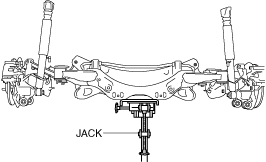
1. Support the rear crossmember component with a jack and remove the rear crossmember installation nuts.
ac5uuw00000195
|
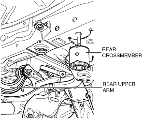
2. Press down on the rear crossmember component slowly until the rear upper arm inside installation bolts can be removed using a jack.
ac5wzw00002326
|
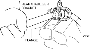
Rear Stabilizer Bracket Removal Note
1. Secure the rear stabilizer bracket flange using a vise.
ac5uuw00006539
|
2. Remove the rear stabilizer bracket.
Suspension Links Installation Note
1. When installing the joint sections with rubber bushings, perform the following procedures:
Rear Stabilizer Bushing, Rear Stabilizer Bracket Installation Note
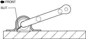
1. Install the rear stabilizer bushing with the slit pointing toward the front of the vehicle.
ac5uuw00000916
|
2. Install the rear stabilizer bracket to the front stabilizer bushing by hand using the following procedure.
3. If the rear stabilizer bracket cannot be installed by hand, install it using a vise.
ac5uuw00001628
|
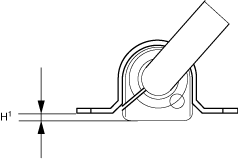
4. During rear stabilizer bracket installation, keep the deviation in the positions of the rear stabilizer bracket and the rear stabilizer bushing within the range shown in the figure.
ac5uuw00000917
|
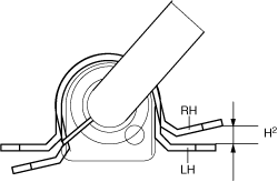
5. After installing the rear stabilizer bracket, verify that the positions of the rear stabilizer bracket and the rear stabilizer bushing are within the range shown in the figure.
ac5uuw00000918
|
6. After installing the rear stabilizer bracket, verify that the right and left-side positions of the rear stabilizer bracket are within the range shown in the figure.
ac5uuw00000919
|
7. Place the rear stabilizer component on a level workbench, and verify that it is within the range shown in the figure.
ac5uuw00000920
|
Rear Stabilizer Component Installation Note
1. Temporarily tighten nuts A and B shown in the figure.
ac5uuw00000162
|
2. Tighten nut A.
3. Tighten nut B.
4. Tighten nut A.
5. Lift up the rear crossmember component using a jack and install the rear crossmember installation nuts.
ac5uuw00000195
|