|
1
|
INSPECT IGNITION RELAY (IG1_STAB) FOR MALFUNCTION
• Switch the ignition off.
• Disconnect the negative battery terminal.
• Remove the ignition relay (IG1_STAB).
• Inspect the ignition relay (IG1_STAB).
• Is the ignition relay (IG1_STAB) normal?
|
Yes
|
Go to the next step.
|
|
No
|
Replace the ignition relay (IG1_STAB), then go to Step 10.
|
|
2
|
PERFORM PCM DTC INSPECTION
• Perform the PCM DTC inspection using the M-MDS.
• Are any DTCs present?
|
Yes
|
Go to the applicable DTC inspection.
|
|
No
|
Go to the next step.
|
|
3
|
PERFORM FRONT BODY CONTROL MODULE (FBCM) DTC INSPECTION
• Perform the front body control module (FBCM) DTC inspection using the M-MDS.
• Are any DTCs present?
|
Yes
|
Go to the applicable DTC inspection.
|
|
No
|
Go to the next step.
|
|
4
|
VERIFY CLIMATE CONTROL UNIT CONNECTOR CONDITION
• Switch the ignition off.
• Disconnect the negative battery terminal.
• Disconnect the climate control unit connector.
• Inspect the connector and terminals (corrosion, damage, pin disconnection).
• Are the connector and terminals normal?
|
Yes
|
Go to the next step.
|
|
No
|
Repair/replace the connector or terminal.
After repair procedure, go to Step 10.
|
|
5
|
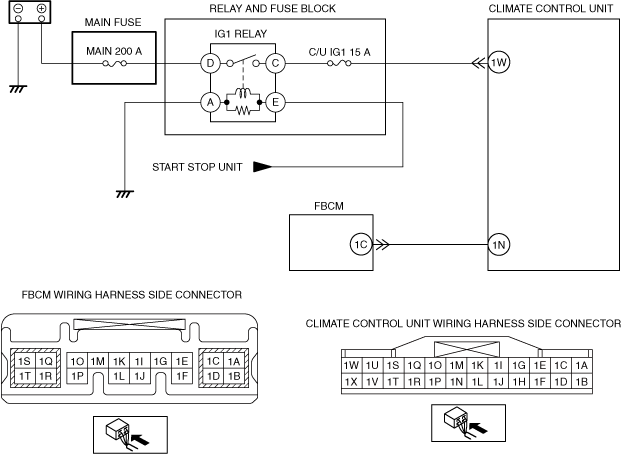
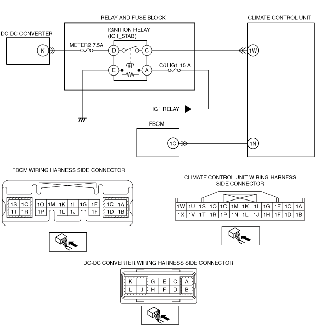
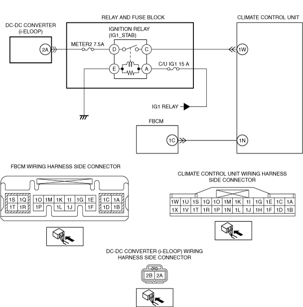
INSPECT CLIMATE CONTROL UNIT POWER SUPPLY VOLTAGE (IG1)
• Climate control unit connector is disconnected.
• Connect the negative battery terminal.
• Switch the ignition ON (engine off or on).
• Measure the voltage at the following terminals (wiring harness-side):
-
― Climate control unit terminal 1W
• Is the voltage B+?
|
Yes
|
Go to the next step.
|
|
No
|
Inspect the METER2 7.5 A fuse.
• If the fuse is blown:
-
― Refer to the wiring diagram and verify whether or not there is a common connector between climate control unit terminal and METER2 7.5 A fuse.
If there is a common connector:
-
• Determine the malfunctioning part by inspecting the common connector and the terminal for corrosion, damage, or pin disconnection, and the common wiring harness for a short to ground.
• Repair or replace the malfunctioning part.
If there is no common connector:
-
• Repair or replace the wiring harness which has a short to ground.
― Replace the fuse.
• If the fuse is damaged:
-
― Replace the fuse.
• If the fuse is normal:
-
― Refer to the wiring diagram and verify whether or not there is a common connector between climate control unit terminal and DC-DC converter (i-ELOOP) terminal.
If there is a common connector:
-
• Determine the malfunctioning part by inspecting the common connector and the terminal for corrosion, damage, or pin disconnection, and the common wiring harness for an open circuit.
• Repair or replace the malfunctioning part.
If there is no common connector:
-
• Repair or replace the wiring harness which has an open circuit.
Then go to Step 10.
|
|
6
|
INSPECT CLIMATE CONTROL UNIT POWER SUPPLY VOLTAGE (IG2)
• Climate control unit connector is disconnected.
• Measure the voltage at the following terminals (wiring harness-side):
-
― Climate control unit terminal 1N
• Is the voltage B+?
|
Yes
|
Go to Step 10.
|
|
No
|
Go to the next step.
|
|
7
|
VERIFY FRONT BODY CONTROL MODULE (FBCM) CONNECTOR CONDITION
• Switch the ignition off.
• Disconnect the negative battery terminal.
• Disconnect the front body control module (FBCM) connector.
• Inspect the connector and terminals (corrosion, damage, pin disconnection).
• Are the connector and terminals normal?
|
Yes
|
Go to the next step.
|
|
No
|
Repair/replace the connector or terminal.
After repair procedure, go to Step 10.
|
|
8
|
INSPECT CLIMATE CONTROL UNIT POWER SUPPLY CIRCUIT (IG2) FOR OPEN CIRCUIT
• Climate control unit and front body control module (FBCM) connectors are disconnected.
• Inspect for continuity between the following terminals (wiring harness-side):
-
― Climate control unit terminal 1N—front body control module (FBCM) terminal 1C
• Is there continuity?
|
Yes
|
Go to the next step.
|
|
No
|
Refer to the wiring diagram and verify whether or not there is a common connector between climate control unit terminal and front body control module (FBCM) terminal.
If there is a common connector:
• Determine the malfunctioning part by inspecting the common connector and the terminal for corrosion, damage, or pin disconnection, and the common wiring harness for an open circuit.
• Repair or replace the malfunctioning part.
If there is no common connector:
• Repair or replace the wiring harness which has an open circuit.
Go to Step 10.
|
|
9
|
INSPECT CLIMATE CONTROL UNIT POWER SUPPLY CIRCUIT (IG2) FOR SHORT TO GROUND
• Climate control unit and front body control module (FBCM) connectors are disconnected.
• Inspect for continuity between the following terminal (wiring harness-side) and body ground:
-
― Climate control unit terminal 1N
• Is there continuity?
|
Yes
|
Refer to the wiring diagram and verify whether or not there is a common connector between climate control unit terminal and front body control module (FBCM) terminal.
If there is a common connector:
• Determine the malfunctioning part by inspecting the common connector and the terminal for corrosion, damage, or pin disconnection, and the common wiring harness for a short to ground.
• Repair or replace the malfunctioning part.
If there is no common connector:
• Repair or replace the wiring harness which has a short to ground.
Go to the next step.
|
|
No
|
Go to the next step.
|
|
10
|
VERIFY THAT SAME DTC IS NOT OUTPUT AGAIN
• Switch the ignition off.
• Disconnect the negative battery terminal.
• Reconnect the disconnected connectors.
• Connect the negative battery terminal.
• Clear the DTC from the climate control unit memory using the M-MDS.
• Perform the DTC inspection for the climate control unit using the M-MDS.
• Is the same DTC displayed?
|
Yes
|
Repeat the inspection from Step 1.
• If the malfunction recurs, replace the climate control unit.
Go to the next step.
|
|
No
|
Go to the next step.
|
|
11
|
VERIFY THAT NO OTHER DTCs ARE PRESENT
• Verify other DTCs displayed.
• Are any other DTCs displayed?
|
Yes
|
Repair or replace the malfunctioning part according to the applicable DTC troubleshooting.
|
|
No
|
DTC troubleshooting completed.
|