|
1
|
VERIFY AFTER-MARKET ELECTRICAL COMPONENT INSTALLATION CONDITION
• Verify if a non-genuine, after-market electrical component is installed.
• Has a non-genuine, after-market electrical component been installed?
|
Yes
|
Go to the next step.
|
|
No
|
Go to Step 3.
|
|
2
|
VERIFY IF MALFUNCTION CAUSE IS AFTER-MARKET ELECTRICAL COMPONENT INSTALLATION
• Disconnect the non-genuine, after-market electrical component connectors.
• Verify if the malfunction symptom recurs as stated by the customer.
• Does the malfunction recur?
|
Yes
|
Go to the next step.
|
|
No
|
Explain to the customer that the malfunction occurred due to the after-market electrical component installation.
|
|
3
|
VERIFY MALFUNCTION SYMPTOM
• Switch the ignition to ACC or ON (engine off or on).
• Launch the on-board diagnostic assist function.
• Select assist code “94”.
• Press the [ENTER] and verify that the sound is output from each speaker.
• Is sound output from each speaker in the order?
|
Yes
|
• System is normal.
• Due to the possibility that sound is not output in some modes, verify the malfunction in the symptom troubleshooting chart and perform the other applicable malfunction diagnosis.
|
|
No
|
No sound is produced from all speakers
• Go to the next step.
No sound is produced from some speakers
• Go to Step 12.
|
|
4
|
INSPECT TAU CONNECTOR
• Disconnect the negative battery terminal.
• Disconnect the TAU connector.
• Inspect the connector engagement and connection condition and inspect the terminals for damage, deformation, corrosion, or disconnection.
• Is the connector normal?
|
Yes
|
Go to the next step.
|
|
No
|
Repair or replace the connector, then go to Step 15.
|
|
5
|
INSPECT AUDIO AMPLIFIER CONNECTOR
• Disconnect the audio amplifier connector.
• Inspect the connector engagement and connection condition and inspect the terminals for damage, deformation, corrosion, or disconnection.
• Is the connector normal?
|
Yes
|
Go to the next step.
|
|
No
|
Repair or replace the connector, then go to Step 15.
|
|
6
|
INSPECT CMU CONNECTOR
• Disconnect the CMU connector.
• Inspect the connector engagement and connection condition and inspect the terminals for damage, deformation, corrosion, or disconnection.
• Is the connector normal?
|
Yes
|
Go to the next step.
|
|
No
|
Repair or replace the connector, then go to Step 15.
|
|
7
|
INSPECT TAU ACC POWER SUPPLY VOLTAGE
• Verify that the TAU connector is disconnected.
• Reconnect the negative battery terminal.
• Switch the ignition to ACC or ON (engine off or on).
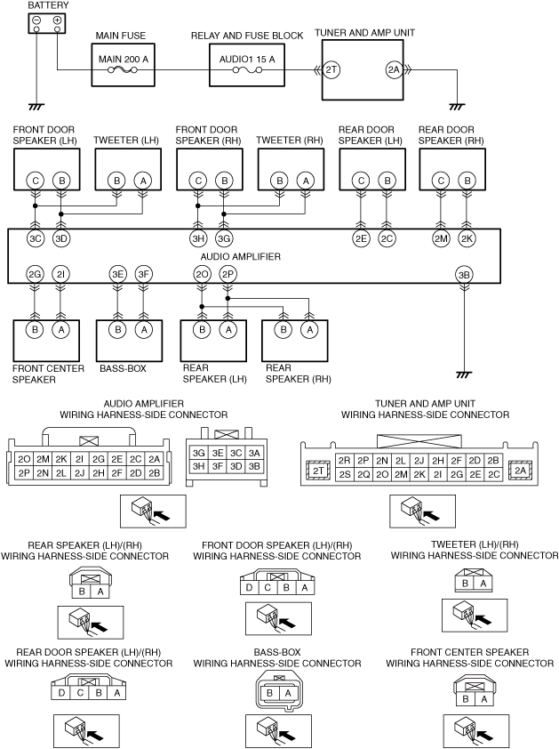
• Measure the voltage at TAU terminal 2T (vehicle wiring harness side).
• Is the voltage B+?
|
Yes
|
Go to the next step.
|
|
No
|
Inspect the AUDIO1 15A fuse.
• If the fuse is blown:
-
― Refer to the wiring diagram and verify if there is a common connector between AUDIO1 15A fuse and the TAU terminal 2T.
If there is a common connector:
-
• Inspect the common connector and terminals for corrosion, damage, or disconnection and the common wiring harnesses for short to ground to determine the malfunctioning location.
• Repair or replace the malfunctioning location.
If there is no common connector:
-
• Repair or replace the wiring harness which is shorted to ground.
• Replace the fuse.
• If the fuse is damaged:
-
― Replace the fuse.
• If the fuse is normal:
-
― Refer to the wiring diagram and verify if there is a common connector between ACC relay and the TAU terminal 2T.
If there is a common connector:
-
• Inspect the common connector and terminals for corrosion, damage, or disconnection and the common wiring harnesses for an open circuit to determine the malfunctioning location.
• Repair or replace the malfunctioning location.
If there is no common connector:
-
• Repair or replace the wiring harness which has an open circuit.
Go to Step 15.
|
|
8
|
VERIFY IF MALFUNCTION CAUSE IS OPEN CIRCUIT IN WIRING HARNESS BETWEEN TAU AND BODY GROUND
• Verify that the TAU connector is disconnected.
• Inspect the wiring harness for continuity between the following terminals (vehicle wiring harness side).
-
― TAU terminal 2A and body ground
• Is there continuity?
|
Yes
|
Go to the next step.
|
|
No
|
• Refer to the wiring diagram and verify if there is a common connector between the following terminals.
-
― TAU terminal 2A and body ground
If there is a common connector:
-
• Inspect the common connector and terminals for corrosion, damage, or disconnection and the common wiring harnesses for an open circuit to determine the malfunctioning location.
• Repair or replace the malfunctioning location.
If there is no common connector:
-
• Repair or replace the wiring harness which has an open circuit.
• Go to Step 15.
|
|
9
|
VERIFY IF MALFUNCTION CAUSE IS OPEN CIRCUIT IN WIRING HARNESS BETWEEN AUDIO AMPLIFIER AND BODY GROUND
• Verify that the audio amplifier connectors are disconnected.
• Inspect the wiring harness for continuity between the following terminals (vehicle wiring harness side).
-
― Audio amplifier terminal 3B and body ground
• Is there continuity?
|
Yes
|
Go to the next step.
|
|
No
|
• Refer to the wiring diagram and verify if there is a common connector between the following terminals.
-
― Audio amplifier terminal 3B and body ground
If there is a common connector:
-
• Inspect the common connector and terminals for corrosion, damage, or disconnection and the common wiring harnesses for an open circuit to determine the malfunctioning location.
• Repair or replace the malfunctioning location.
If there is no common connector:
-
• Repair or replace the wiring harness which has an open circuit.
• Go to Step 15.
|
|
10
|
DETERMINE IF MALFUNCTION CAUSE IS AUDIO AMPLIFIER
• Disconnect the negative battery terminal.
• Replace the audio amplifier.
• Connect all the connectors.
• Reconnect the negative battery terminal.
• Switch the ignition to ACC or ON (engine off or on).
• Launch the on-board diagnostic assist function.
• Select assist code “94”.
• Press the [ENTER] and verify that the sound is output from each speaker.
• Is sound output from each speaker in the order?
|
Yes
|
Go to Step 15.
|
|
No
|
Go to the next step.
|
|
11
|
DETERMINE IF MALFUNCTION CAUSE IS TAU
• Disconnect the negative battery terminal.
• Connect all the connectors.
• Reconnect the negative battery terminal.
• Switch the ignition to ACC or ON (engine off or on).
• Launch the on-board diagnostic assist function.
• Select assist code “94”.
• Press the [ENTER] and verify that the sound is output from each speaker.
• Is sound output from each speaker in the order?
|
Yes
|
Go to Step 15.
|
|
No
|
Replace the CMU, then go to Step 15.
|
|
12
|
INSPECT SPEAKERS
• Disconnect the negative battery terminal.
• Inspect the malfunctioning speaker.
• Is the speaker resistance normal?
|
Yes
|
Go to the next step.
|
|
No
|
Replace the malfunctioning speaker, then go to Step 15.
|
|
13
|
INSPECT SPEAKER CIRCUIT FOR OPEN CIRCUIT
• Disconnect the connector of the malfunctioning speaker and the audio amplifier connector.
• Verify the continuity of the wiring harness between the following terminals (vehicle wiring harness side) of the speakers which are malfunctioning.
-
― Audio amplifier terminal 3G and front door speaker (LH) terminal B
― Audio amplifier terminal 3H and front door speaker (LH) terminal C
― Audio amplifier terminal 3H and tweeter (LH) terminal B
― Audio amplifier terminal 3G and tweeter (LH) terminal A
― Audio amplifier terminal 3D and front door speaker (RH) terminal B
― Audio amplifier terminal 3C and front door speaker (RH) terminal C
― Audio amplifier terminal 3D and tweeter (RH) terminal A
― Audio amplifier terminal 3C and tweeter (RH) terminal B
― Audio amplifier terminal 2K and rear door speaker (LH) terminal B
― Audio amplifier terminal 2M and rear door speaker (LH) terminal C
― Audio amplifier terminal 2E and rear door speaker (RH) terminal C
― Audio amplifier terminal 2C and rear door speaker (RH) terminal B
― Audio amplifier terminal 2G and front center speaker terminal B
― Audio amplifier terminal 2I and front center speaker terminal A
― Audio amplifier terminal 2O and rear speaker (LH) terminal B
― Audio amplifier terminal 2P and rear speaker (LH) terminal A
― Audio amplifier terminal 2O and rear speaker (RH) terminal B
― Audio amplifier terminal 2P and rear speaker (RH) terminal A
― Audio amplifier terminal 3E and base-box terminal B
― Audio amplifier terminal 3F and base-box terminal A
• Is there continuity?
|
Yes
|
Go to the next step.
|
|
No
|
• Refer to the wiring diagram and verify if there is a common connector between the following terminals.
-
― Audio amplifier terminal 3G and front door speaker (LH) terminal B
― Audio amplifier terminal 3H and front door speaker (LH) terminal C
― Audio amplifier terminal 3H and tweeter (LH) terminal B
― Audio amplifier terminal 3G and tweeter (LH) terminal A
― Audio amplifier terminal 3D and front door speaker (RH) terminal B
― Audio amplifier terminal 3C and front door speaker (RH) terminal C
― Audio amplifier terminal 3D and tweeter (RH) terminal A
― Audio amplifier terminal 3C and tweeter (RH) terminal B
― Audio amplifier terminal 2K and rear door speaker (LH) terminal B
― Audio amplifier terminal 2M and rear door speaker (LH) terminal C
― Audio amplifier terminal 2E and rear door speaker (RH) terminal C
― Audio amplifier terminal 2C and rear door speaker (RH) terminal B
― Audio amplifier terminal 2G and front center speaker terminal B
― Audio amplifier terminal 2I and front center speaker terminal A
― Audio amplifier terminal 2O and rear speaker (LH) terminal B
― Audio amplifier terminal 2P and rear speaker (LH) terminal A
― Audio amplifier terminal 2O and rear speaker (RH) terminal B
― Audio amplifier terminal 2P and rear speaker (RH) terminal A
― Audio amplifier terminal 3E and base-box terminal B
― Audio amplifier terminal 3F and base-box terminal A
If there is a common connector:
-
― Inspect the common connector and terminals for corrosion, damage, or disconnection and the common wiring harnesses for an open circuit to determine the malfunctioning location.
― Repair or replace the malfunctioning location.
If there is no common connector:
-
― Repair or replace the wiring harness which has an open circuit.
• Go to Step 15.
|
|
14
|
INSPECT SPEAKER CIRCUIT FOR SHORT TO GROUND
• Verify that the connector of the malfunctioning speaker and the audio amplifier connector are disconnected.
• Inspect for continuity between the following terminals (vehicle wiring harness side) of the speakers which are malfunctioning and body ground.
-
― Front door speaker (LH) terminal B
― Front door speaker (LH) terminal C
― Tweeter (LH) terminal B
― Tweeter (LH) terminal A
― Front door speaker (RH) terminal B
― Front door speaker (RH) terminal C
― Tweeter (RH) terminal A
― Tweeter (RH) terminal B
― Rear door speaker (LH) terminal B
― Rear door speaker (LH) terminal C
― Rear door speaker (RH) terminal C
― Rear door speaker (RH) terminal B
― Front center speaker terminal B
― Front center speaker terminal A
― Rear speaker (LH) terminal B
― Rear speaker (LH) terminal A
― Rear speaker (RH) terminal B
― Rear speaker (RH) terminal A
― Rear speaker (RH) terminal A
― Base-box terminal B
― Base-box terminal A
• Is there continuity?
|
Yes
|
• Refer to the wiring diagram and verify if there is a common connector between the following terminals.
-
― Audio amplifier terminal 3G and front door speaker (LH) terminal B
― Audio amplifier terminal 3H and front door speaker (LH) terminal C
― Audio amplifier terminal 3H and tweeter (LH) terminal B
― Audio amplifier terminal 3G and tweeter (LH) terminal A
― Audio amplifier terminal 3D and front door speaker (RH) terminal B
― Audio amplifier terminal 3C and front door speaker (RH) terminal C
― Audio amplifier terminal 3D and tweeter (RH) terminal A
― Audio amplifier terminal 3C and tweeter (RH) terminal B
― Audio amplifier terminal 2K and rear door speaker (LH) terminal B
― Audio amplifier terminal 2M and rear door speaker (LH) terminal C
― Audio amplifier terminal 2E and rear door speaker (RH) terminal C
― Audio amplifier terminal 2C and rear door speaker (RH) terminal B
― Audio amplifier terminal 2G and front center speaker terminal B
― Audio amplifier terminal 2I and front center speaker terminal A
― Audio amplifier terminal 2O and rear speaker (LH) terminal B
― Audio amplifier terminal 2P and rear speaker (LH) terminal A
― Audio amplifier terminal 2O and rear speaker (RH) terminal B
― Audio amplifier terminal 2P and rear speaker (RH) terminal A
― Audio amplifier terminal 3E and base-box terminal B
― Audio amplifier terminal 3F and base-box terminal A
If there is a common connector:
-
― Inspect the common connector and terminals for corrosion, damage, or disconnection and the common wiring harnesses for short to ground to determine the malfunctioning location.
― Repair or replace the malfunctioning location.
If there is no common connector:
-
― Repair or replace the wiring harness which is shorted to ground.
• Go to the next step.
|
|
No
|
Go to the next step.
|
|
15
|
VERIFY IF MALFUNCTION CAUSE IS CORRECTED
• Disconnect the negative battery terminal.
• Connect all the connectors.
• Reconnect the negative battery terminal.
• Switch the ignition to ACC or ON (engine off or on).
• Launch the on-board diagnostic assist function.
• Select assist code “94”.
• Press the [ENTER] and verify that the sound is output from each speaker.
• Is sound output from each speaker in the order?
|
Yes
|
Troubleshooting completed (explain the contents of the servicing to the customer).
|
|
No
|
Verify the malfunction symptom in the symptom troubleshooting chart and perform the other applicable malfunction diagnosis.
|