49 L067 006
Plum-bob

49 JP04 001
Target marker

SIDE CAMERA AIMING
id092000497900
Special Service Tool (SST)
|
49 L067 006
Plum-bob
|
|
49 JP04 001
Target marker
|
|
1. Empty the vehicle by having all occupants leave the vehicle and remove all the cargo except for the spare tire, jack and tools.
2. Adjust the air pressure of each tire to the specified value. (See WHEEL AND TIRE SPECIFICATION.)
3. Move the vehicle to level ground.
ac5wzw00009581
|
4. Perform the DTC inspection for the parking assist unit (optical) using the M-MDS and verify that no DTCs are displayed. (See DTC INSPECTION [PARKING ASSIST UNIT (OPTICAL)].)
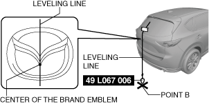
5. Adjust the SST (plum-bob) so that it is aligned with the center of the brand emblem, determine the center position at the front of the vehicle, and mark the center position (point A) on the floor surface.
ac5wzw00009582
|
6. Adjust the SST (plum-bob) so that it is aligned with the center of the brand emblem, determine the center position at the rear of the vehicle, and mark the center position (point B) on the floor surface.
ac5wzw00009583
|
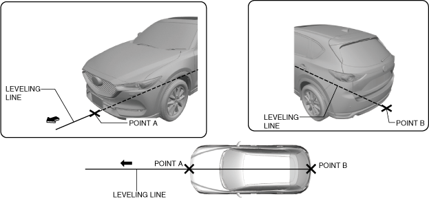
7. Secure the end of the leveling line over point B.
ac5wzw00009584
|
8. Pull the unsecured end of the leveling line over the vehicle and to the front and adjust it so that it passes over point A.
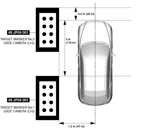
9. Position the SSTs (target marker) at the positions shown in the figure.
ac5wzw00009585
|
10. Connect the M-MDS to the DLC-2.
11. After the vehicle is identified, select the following items from the initial screen of the M-MDS.
12. Perform the side camera aiming procedure according to the directions on the M-MDS.
13. Verify the M-MDS display.
|
Error code |
Detection condition |
|---|---|
|
01
|
Target marker set position or input value is incorrect
|
|
02
|
Visibility where aiming is performed is bright or dark, target soiled
|
|
03
|
Target marker is not detected
|
|
04
|
Target marker moves during aiming
|
|
05
|
Input vehicle value exceeds specification
|
|
06
|
Aiming result is required during aiming
|
|
07
|
Power outer mirrors are folded
|
|
08
|
Aiming result is required for parking assist unit (optical) with aiming not completed
|
|
09
|
Parking assist unit (optical) internal malfunction
|
Error code 01/05
|
Step |
Inspection |
Action |
|
|---|---|---|---|
|
1
|
VERIFY TARGET MARKER POSITION
• Verify the following:
• Display the screen of the side monitor in the center display by pressing the monitor switch.
• Is there any malfunction?
|
Yes
|
Repair the target marker for malfunction and go to the next step.
|
|
No
|
Go to the next step.
|
||
|
2
|
PERFORM SIDE CAMERA AIMING
• Perform the side camera aiming.
• Is the side camera aiming completed normally?
|
Yes
|
Side camera aiming is completed.
|
|
No
|
Error code 01 or 05 is displayed
• Go to the next step.
Code other than error cord 01 or 05 is displayed
• Go to the procedure for the displayed error code.
|
||
|
3
|
VERIFY DTC
• Perform the DTC inspection for the parking assist unit (optical).
• Is the DTC displayed?
|
Yes
|
• Go to the applicable DTC inspection.
• After the diagnostic procedure is completed, perform the side camera aiming.
|
|
No
|
Re-perform the side camera aiming, and replace the FSC if the side camera aiming is not completed normally.
|
||
Error code 02/03/04
|
Step |
Inspection |
Action |
|
|---|---|---|---|
|
1
|
VERIFY TARGET MARKER SETTING ENVIRONMENT
• Verify the following:
• Display the screen of the side monitor in the center display by pressing the monitor switch.
• Is there any malfunction?
|
Yes
|
Repair the malfunctioning part and go to the next step.
|
|
No
|
Go to the next step.
|
||
|
2
|
PERFORM SIDE CAMERA AIMING
• Perform the side camera aiming.
• Is the side camera aiming completed normally?
|
Yes
|
Side camera aiming is completed.
|
|
No
|
Error code 02 or 03 or 04 is displayed
• Go to the next step.
Code other than error cord 02 or 03 or 04 is displayed
• Go to the procedure for the displayed error code.
|
||
|
3
|
VERIFY DTC
• Perform the DTC inspection for the parking assist unit (optical).
• Is the DTC displayed?
|
Yes
|
• Go to the applicable DTC inspection.
• After the diagnostic procedure is completed, perform the side camera aiming.
|
|
No
|
Re-perform the side camera aiming, and replace the FSC if the side camera aiming is not completed normally.
|
||
Error code 06/08/09
|
Step |
Inspection |
Action |
|
|---|---|---|---|
|
1
|
PERFORM SIDE CAMERA AIMING
• Perform the side camera aiming.
• Is the side camera aiming completed normally?
|
Yes
|
Sside camera aimingide camera aiming is completed.
|
|
No
|
Error code 06 or 08 or 09 is displayed
• Go to the next step.
Code other than error cord 06 or 08 or 09 is displayed
• Go to the procedure for the displayed error code.
|
||
|
2
|
VERIFY DTC
• Perform the DTC inspection for the parking assist unit (optical).
• Is the DTC displayed?
|
Yes
|
• Go to the applicable DTC inspection.
• After the diagnostic procedure is completed, perform the side camera aiming.
|
|
No
|
Re-perform the side camera aiming, and replace the FSC if the side camera aiming is not completed normally.
|
||
Error code 07
|
Step |
Inspection |
Action |
|
|---|---|---|---|
|
1
|
VERIFY POWER OUTER MIRROR FOLD/UNFOLD CONDITION
• Are the power outer mirrors unfolded?
|
Yes
|
Go to the next step.
|
|
No
|
Unfold the power outer mirrors, then go to the next step.
|
||
|
2
|
PERFORM SIDE CAMERA AIMING
• Perform the side camera aiming.
• Is the side camera aiming completed normally?
|
Yes
|
Side camera aiming is completed.
|
|
No
|
Error code 07 is displayed
• Go to the next step.
Code other than error cord 07 is displayed
• Go to the procedure for the displayed error code.
|
||
|
3
|
VERIFY DTC
• Perform the DTC inspection for the parking assist unit (optical).
• Is the DTC displayed?
|
Yes
|
• Go to the applicable DTC inspection.
• After the diagnostic procedure is completed, perform the side camera aiming.
|
|
No
|
Re-perform the side camera aiming, and replace the FSC if the side camera aiming is not completed normally.
|
||