 |
ac5wzw00010255
FUEL GAUGE SENDER UNIT INSPECTION [2WD]
id0922000121b2
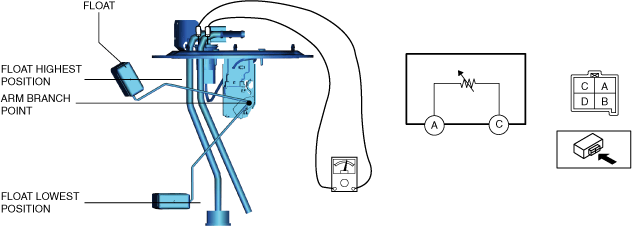
Fuel gauge sender unit connector 4-pin type
SKYACTIV-G 2.0, SKYACTIV-G 2.5, SKYACTIV-G 2.5T
1. Verify that the resistance at fuel gauge sender unit terminals D and C is as follows according to the height of the float.
ac5wzw00010255
|
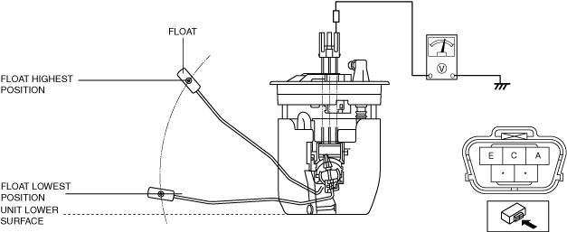
Fuel gauge sender unit connector 5-pin type
SKYACTIV-G 2.0 (WITHOUT CYLINDER DEACTIVATION)
1. Apply 5 V to fuel gauge sender unit terminals A.
2. Verify the voltage of fuel gauge sender unit terminal E.
am3zzw00020163
|
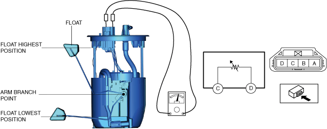
SKYACTIV-D 2.2
1. Perform the "Fuel Line Safety Procedure" referring to the "BEFORE SERVICE PRECAUTION". (See BEFORE SERVICE PRECAUTION [SKYACTIV-D 2.2].)
2. If the fuel gauge level indicates 3/4 or more, refer to the "FUEL DRAINING PROCEDURE" and drain the fuel. (See FUEL DRAINING PROCEDURE [SKYACTIV-D 2.2].)
3. Disconnect the negative battery terminal. (See NEGATIVE BATTERY TERMINAL DISCONNECTION/CONNECTION.)
4. Remove the following parts:
5. Remove the fuel gauge sender unit. (See FUEL GAUGE SENDER UNIT REMOVAL/INSTALLATION [2WD].)
6. Verify that the resistance at fuel gauge sender unit terminals C and A is as follows according to the height of the float.
ac5wzw00012919
|