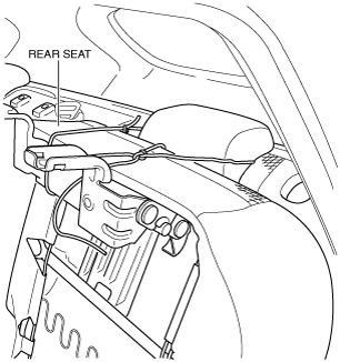
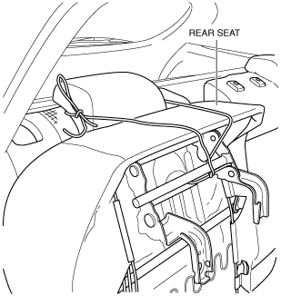
1. Set the rear seat aside as shown in the figure. (See REAR SEAT REMOVAL/INSTALLATION.)
ac5uuw00000410
|
FUEL TANK INSPECTION [SKYACTIV-G 2.0, SKYACTIV-G 2.5]
id0114z9803200
2WD
1. Level the vehicle.
2. Complete the “BEFORE SERVICE PRECAUTION”. (See BEFORE SERVICE PRECAUTION [SKYACTIV-G 2.0, SKYACTIV-G 2.5].)
3. Drain the fuel. (See FUEL DRAINING PROCEDURE [SKYACTIV-G 2.0, SKYACTIV-G 2.5].)
4. Using the following procedure:
ac5uuw00000410
|
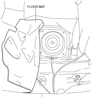
5. Partially peel back the floor mat as shown in the figure.
ac5uuw00000411
|
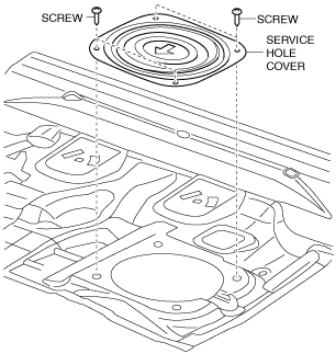
6. Remove the service hole cover.
ac5uuw00000412
|
7. Disconnect the following parts:
8. Remove the floor under cover. (See FLOOR UNDER COVER REMOVAL/INSTALLATION.)
9. Disconnect the HO2S connector.
10. Remove the TWC and HO2S as a single unit. (See EXHAUST SYSTEM REMOVAL/INSTALLATION [SKYACTIV-G 2.0, SKYACTIV-G 2.5])
11. Remove the fuel tank and fuel pump unit as a single unit. (See FUEL TANK REMOVAL/INSTALLATION [SKYACTIV-G 2.0, SKYACTIV-G 2.5])
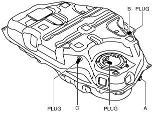
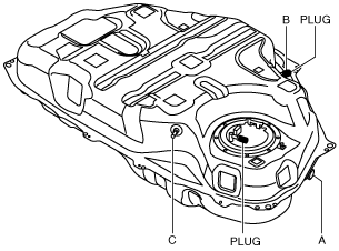
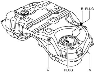
12. Perform the following procedure to verify the fuel tank airtightness.
ac5uuw00000413
|
13. Plug the fuel pump unit pipe and port B.
ac5uuw00000414
|
14. Level the fuel tank.
15. Apply a pressure of 3 kPa {23 mmHg, 0.9 inHg} to port A and wait for a while.
16. With the pressure still applied, verify that there is air flow from port C and the pressure is 0—3 kPa {0—23 mmHg, 0—0.9 inHg}.
17. Apply a pressure of -0.5 kPa {-3.8 mmHg, -0.1 inHg} to port A and wait for a while.
18. With the pressure still applied, verify that there is air flow from port C and the pressure is -0.5—0 kPa {-3.8—0 mmHg, -0.1—0 inHg}.
19. Apply a pressure to port A and wait for a while.
ac5uuw00000415
|
20. With the pressure still applied, verify that there is no air flow from port C.
4WD
1. Level the vehicle.
2. Complete the “BEFORE SERVICE PRECAUTION”. (See BEFORE SERVICE PRECAUTION [SKYACTIV-G 2.0, SKYACTIV-G 2.5].)
3. Drain the fuel. (See FUEL DRAINING PROCEDURE [SKYACTIV-G 2.0, SKYACTIV-G 2.5].)
4. Using the following procedure:
Main side
ac5uuw00000410
|
Sub side
ac5uuw00000416
|
5. Partially peel back the floor mat as shown in the figure.
Main side
ac5uuw00000411
|
Sub side
ac5uuw00000417
|
6. Remove the service hole cover.
Main side
ac5uuw00000412
|
Sub side
ac5uuw00000418
|
7. Disconnect the following parts:
8. Remove the floor under cover. (See FLOOR UNDER COVER REMOVAL/INSTALLATION.)
9. Disconnect the HO2S connector.
10. Remove the TWC and HO2S as a single unit. (See EXHAUST SYSTEM REMOVAL/INSTALLATION [SKYACTIV-G 2.0, SKYACTIV-G 2.5])
11. Remove the propeller shaft. (See PROPELLER SHAFT REMOVAL/INSTALLATION.)
12. Remove the fuel tank, fuel pump unit and fuel gauge sender unit (sub) as a single unit. (See FUEL TANK REMOVAL/INSTALLATION [SKYACTIV-G 2.0, SKYACTIV-G 2.5])
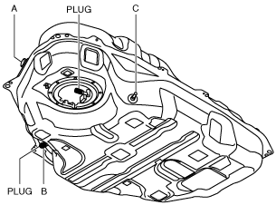
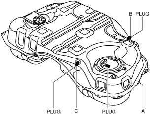
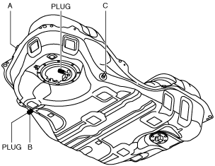
13. Perform the following procedure to verify the fuel tank airtightness.
ac5uuw00000419
|
14. Plug the fuel pump unit pipe and port B.
ac5uuw00000420
|
15. Level the fuel tank.
16. Apply a pressure of 3 kPa {23 mmHg, 0.9 inHg} to port A and wait for a while.
17. With the pressure still applied, verify that there is air flow from port C and the pressure is 0—3 kPa {0—23 mmHg, 0—0.9 inHg}.
18. Apply a pressure of -0.5 kPa {-3.8 mmHg, -0.1 inHg} to port A and wait for a while.
19. With the pressure still applied, verify that there is air flow from port C and the pressure is -0.5—0 kPa {-3.8—0 mmHg, -0.1—0 inHg}.
20. Apply a pressure to port A and wait for a while.
ac5uuw00000421
|
21. With the pressure still applied, verify that there is no air flow from port C.