|
1
|
VERIFY FRONT BODY CONTROL MODULE (FBCM) DTCs AGAIN
• Clear front body control module (FBCM) DTCs using the M-MDS.
• Switch the ignition ON (engine off or on).
• Perform the front body control module (FBCM) DTC inspection using the M-MDS.
• Is DTC B1D07:13 displayed?
|
Yes
|
Go to the next step.
|
|
No
|
Go to Step 12.
|
|
2
|
INSPECT FRONT COMBINATION LIGHT (RH) CONNECTOR CONDITION
• Switch the ignition to off.
• Disconnect the negative battery cable.
• Disconnect the front combination light (RH) connector.
• Inspect the connector engagement and connection condition and inspect the terminals for damage, deformation, corrosion, or disconnection.
• Is the connector normal?
|
Yes
|
Go to the next step.
|
|
No
|
Repair or replace the connector, then go to Step 11.
|
|
3
|
INSPECT POWER OUTER MIRROR (RH) CONNECTOR CONDITION
• Disconnect the power outer mirror (RH) connector.
• Inspect the connector engagement and connection condition and inspect the terminals for damage, deformation, corrosion, or disconnection.
• Is the connector normal?
|
Yes
|
Go to the next step.
|
|
No
|
Repair or replace the connector, then go to Step 11.
|
|
4
|
INSPECT REAR TURN LIGHT (RH) CONNECTOR CONDITION
• Disconnect the rear turn light (RH) connector.
• Inspect the connector engagement and connection condition and inspect the terminals for damage, deformation, corrosion, or disconnection.
• Is the connector normal?
|
Yes
|
Go to the next step.
|
|
No
|
Repair or replace the connector, then go to Step 11.
|
|
5
|
INSPECT FRONT BODY CONTROL MODULE (FBCM) CONNECTOR CONDITION
• Disconnect the front body control module (FBCM) connector.
• Inspect the connector engagement and connection condition and inspect the terminals for damage, deformation, corrosion, or disconnection.
• Is the connector normal?
|
Yes
|
Go to the next step.
|
|
No
|
Repair or replace the connector, then go to Step 11.
|
|
6
|
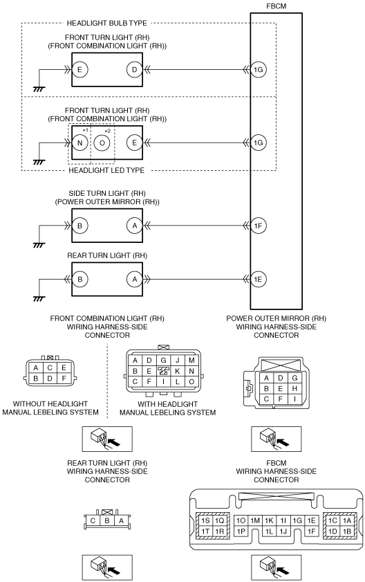
INSPECT TURN LIGHT (RH) CONTROL CIRCUIT FOR SHORT TO POWER SUPPLY
• Verify that the front combination light (RH), power outer mirror (RH), rear turn light (RH), and front body control module (FBCM) connectors are disconnected.
• Connect the negative battery cable.
• Switch the ignition ON (engine off or on).
• Measure the voltage at the following terminals (vehicle wiring harness side).
-
― Front body control module (FBCM) terminal 1G
― Front body control module (FBCM) terminal 1F
― Front body control module (FBCM) terminal 1E
• Is the voltage 0 V?
|
Yes
|
Go to the next step.
|
|
No
|
Repair or replace the wiring harness, then go to Step 11.
|
|
7
|
INSPECT TURN LIGHT (RH) CONTROL CIRCUIT FOR OPEN CIRCUIT
• Verify that the front combination light (RH), power outer mirror (RH), rear turn light (RH), and front body control module (FBCM) connectors are disconnected.
• Switch the ignition to off.
• Disconnect the negative battery cable.
• Inspect the wiring harness between the following terminals (vehicle wiring harness side) for continuity.
-
― Front combination light (RH) terminal D and front body control module (FBCM) terminal 1G (headlight bulb type)
― Front combination light (RH) terminal E and front body control module (FBCM) terminal 1G (headlight LED type)
― Power outer mirror (RH) terminal A and front body control module (FBCM) terminal 1F
― Rear turn light (RH) terminal A and front body control module (FBCM) terminal 1E
• Is there continuity?
|
Yes
|
Go to the next step.
|
|
No
|
Repair or replace the wiring harness, then go to Step 11.
|
|
8
|
INSPECT SIDE TURN LIGHT (RH)
• Inspect the side turn light (RH).
• Is the side turn light (RH) normal?
|
Yes
|
Go to the next step.
|
|
No
|
Replace the side turn light (RH), then go to Step 11.
|
|
9
|
PERFORM DTC INSPECTION AND VERIFY IF MALFUNCTIONING PART IS REAR TURN LIGHT (RH)
• Clear front body control module (FBCM) DTCs using the M-MDS.
• Switch the ignition ON (engine off or on).
• Perform the front body control module (FBCM) DTC inspection using the M-MDS.
• Is DTC B1D07:13 displayed?
|
Yes
|
Replace the rear turn light bulb (RH), then go to the next step.
|
|
No
|
Go to Step 12.
|
|
10
|
PERFORM DTC INSPECTION AND VERIFY IF MALFUNCTIONING PART IS FRONT TURN LIGHT (RH)
• Clear front body control module (FBCM) DTCs using the M-MDS.
• Switch the ignition ON (engine off or on).
• Perform the front body control module (FBCM) DTC inspection using the M-MDS.
• Is DTC B1D07:13 displayed?
|
Yes
|
Replace the front turn light bulb (RH), then go to the next step.
|
|
No
|
Go to Step 12.
|
|
11
|
VERIFY THAT REPAIRS HAVE BEEN COMPLETED
• Reconnect all the disconnected connectors.
• Reconnect the disconnected negative battery cable.
• Clear front body control module (FBCM) DTCs using the M-MDS.
• Switch the ignition ON (engine off or on).
• Perform the front body control module (FBCM) DTC inspection using the M-MDS.
• Is DTC B1D07:13 displayed?
|
Yes
|
Repeat the inspection from Step 1.
• If the malfunction recurs, replace the front body control module (FBCM), then go to the next step.
|
|
No
|
Go to the next step.
|
|
12
|
VERIFY IF OTHER DTCs DISPLAYED
• Are any other DTCs displayed?
|
Yes
|
Repair the malfunctioning part according to the applicable DTC troubleshooting.
|
|
No
|
DTC troubleshooting completed.
|