 |
ac5wzw00007688
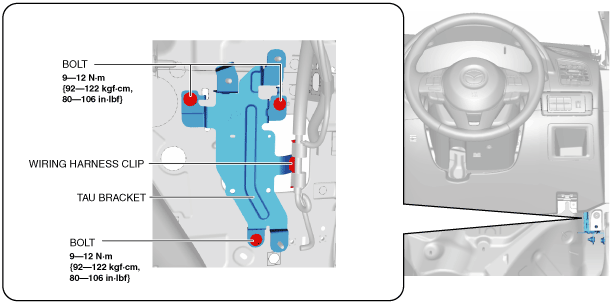
TUNER AND AMP UNIT (TAU) BRACKET REMOVAL/INSTALLATION
id092000014300
L.H.D.
1. Disconnect the negative battery cable. (See NEGATIVE BATTERY CABLE DISCONNECTION/CONNECTION [SKYACTIV-G 2.0, SKYACTIV-G 2.5].) (See NEGATIVE BATTERY CABLE DISCONNECTION/CONNECTION [SKYACTIV-G 2.0, SKYACTIV-G 2.5 (WITHOUT i-stop)].) (See NEGATIVE BATTERY CABLE DISCONNECTION/CONNECTION [SKYACTIV-D 2.2].)
2. Remove the following parts:
3. Pull out the wiring harness clip.
ac5wzw00007688
|
4. Remove the bolts.
5. Remove the TAU bracket.
6. Install in the reverse order of removal.
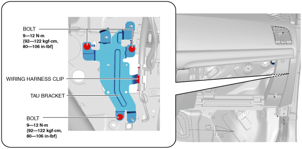
R.H.D.
1. Disconnect the negative battery cable. (See NEGATIVE BATTERY CABLE DISCONNECTION/CONNECTION [SKYACTIV-G 2.0, SKYACTIV-G 2.5].) (See NEGATIVE BATTERY CABLE DISCONNECTION/CONNECTION [SKYACTIV-G 2.0, SKYACTIV-G 2.5 (WITHOUT i-stop)].) (See NEGATIVE BATTERY CABLE DISCONNECTION/CONNECTION [SKYACTIV-D 2.2].)
2. Remove the following parts:
3. Pull out the wiring harness clip.
ac5wzw00007689
|
4. Remove the bolts.
5. Remove the TAU bracket.
6. Install in the reverse order of removal.