FUEL GAUGE SENDER UNIT INSPECTION [2WD]
id092200012101
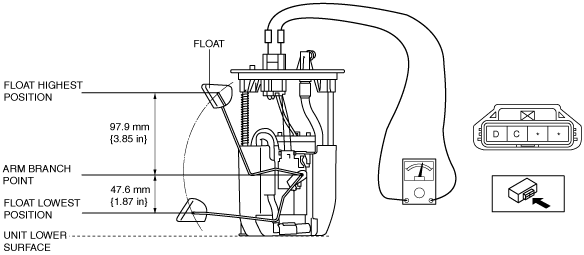
Fuel gauge sender unit connector 4-pin type
SKYACTIV-G 2.0, SKYACTIV-G 2.5
-
Note
-
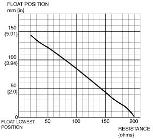
1. Verify that the resistance at fuel gauge sender unit terminals D and C is as indicated in the table according to the height of the float.
-
• If not as indicated in the table, replace the fuel gauge sender unit.
SKYACTIV-D 2.2
1. Disconnect the negative battery cable. (See NEGATIVE BATTERY CABLE DISCONNECTION/CONNECTION [SKYACTIV-D 2.2].)
2. Remove the following parts:
- (1) Rear seat cushion (6:4 split-type seat) (See REAR SEAT CUSHION REMOVAL/INSTALLATION.)
- (2) Rear seat under installation bolt (4:2:4 split-type seat) (See REAR SEAT REMOVAL/INSTALLATION.)
- (3) Rear scuff plate (See REAR SCUFF PLATE REMOVAL/INSTALLATION.)
- (4) Fuel gauge sender unit (See FUEL GAUGE SENDER UNIT REMOVAL/INSTALLATION [2WD].)
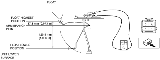
3. Verify that the resistance at fuel gauge sender unit terminals A and C is as indicated in the table according to the height of the float.
-
• If not as indicated in the table, replace the fuel gauge sender unit.
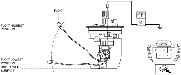
Fuel gauge sender unit connector 5-pin type
-
Warning
-
• Fuel is very flammable liquid. If fuel spills or leaks from the pressurized fuel system, it will cause serious injury or death and facility breakage. Fuel can also irritate skin and eyes. To prevent this, always complete the “Fuel Line Safety Procedure”, while referring to “BEFORE SERVICE PRECAUTION”.
• A person charged with static electricity could cause a fire or explosion, resulting in death or serious injury. Before draining fuel, make sure to discharge static electricity by touching the vehicle body.
-
Note
-
1. Apply 5 V to fuel gauge sender unit terminals A.
2. Verify the voltage of fuel gauge sender unit terminal E.
-
Voltage when float is in the highest position
-
• 4.4—4.6 V
-
Voltage when float is in the lowest position
-
• 0.4—0.6 V
• If the voltage is not within the specification, replace the fuel gauge sender unit.