 |
ac5wzw00014750
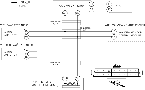
DETERMINING SHORT BETWEEN CIRCUITS LOCATION (CAN-BUS No.3) [TYPE-B (L.H.D.)]
id100270002800
System Wiring Diagram
ac5wzw00014750
|
Determination Procedure
|
Step |
Inspection |
Action |
|
|---|---|---|---|
|
1
|
INSPECT BETWEEN GATEWAY UNIT (GWU) AND DLC-2 FOR SHORT BETWEEN CIRCUITS
• Switch the ignition off.
• Disconnect the negative battery cable.
• Disconnect the connector 3 which has gateway unit (GWU) terminals 3T and 3S.
• Inspect for continuity between gateway unit (GWU) terminals 3T and 3S (wiring harness side).
• Is there continuity?
|
Yes
|
Repair or replace the wiring harness between gateway unit (GWU) and DLC-2 because the wiring harness is shorted between circuits.
|
|
No
|
Go to the next step.
|
||
|
2
|
INSPECT GATEWAY UNIT (GWU) FOR SHORT BETWEEN CIRCUITS
• Disconnect the connector 4 which has gateway unit (GWU) terminals 4R and 4Q.
• Connect the negative battery cable.
• Switch the ignition ON (engine off).
• Measure the voltage at gateway unit (GWU) terminals 4R and 4Q (wiring harness side).
• Is the voltage at gateway unit (GWU) terminals 4R and 4Q (wiring harness side) the same?
|
Yes
|
Go to the next step.
|
|
No
|
Replace the gateway unit (GWU) because there is a short between circuits in the gateway unit (GWU).
|
||
|
3
|
INSPECT BETWEEN GATEWAY UNIT (GWU) AND CONNECTOR C-17 FOR SHORT BETWEEN CIRCUITS
• Switch the ignition off.
• Disconnect the negative battery terminal.
• Disconnect the connector C-17.
• Connect the connector 3 which has gateway unit (GWU) terminals 3T and 3S.
• Connect the connector 4 which has gateway unit (GWU) terminals 4R and 4Q.
• Connect the negative battery terminal.
• Switch the ignition ON (engine off).
• Measure the voltage at DLC-2 terminals F and E.
• Is the voltage at DLC-2 terminals F and E the same?
|
Yes
|
Repair or replace the wiring harness between gateway unit (GWU) and connector C-17 because the wiring harness is shorted between circuits.
|
|
No
|
Go to the next step.
|
||
|
4
|
INSPECT BETWEEN CONNECTOR C-17 AND CONNECTOR C-71 FOR SHORT BETWEEN CIRCUITS
• Switch the ignition off.
• Disconnect the negative battery terminal.
• Disconnect the connector C-71.
• Connect the connector C-17.
• Connect the negative battery terminal.
• Switch the ignition ON (engine off).
• Measure the voltage at DLC-2 terminals F and E.
• Is the voltage at DLC-2 terminals F and E the same?
|
Yes
|
Repair or replace the wiring harness between connector C-17 and connector C-71 because the wiring harness is shorted between circuits.
|
|
No
|
Go to the next step.
|
||
|
5
|
INSPECT BETWEEN AUDIO AMPLIFIER AND CONNECTOR C-71 FOR SHORT BETWEEN CIRCUITS
• Switch the ignition off.
• Disconnect the negative battery terminal.
• Inspect for continuity between audio amplifier terminals 2N and 2M. (with Bose® type audio)
• Inspect for continuity between audio amplifier terminals 1Q and 1S. (without Bose® type audio)
• Is there continuity?
|
Yes
|
Go to the next step.
|
|
No
|
Go to Step 7.
|
||
|
6
|
INSPECT AUDIO AMPLIFIER FOR SHORT BETWEEN CIRCUITS
• Disconnect the audio amplifier connector.
• Inspect for continuity between audio amplifier terminals 2N and 2M (wiring harness side). (with Bose® type audio)
• Inspect for continuity between audio amplifier terminals 1Q and 1S (wiring harness side). (without Bose® type audio)
• Is there continuity?
|
Yes
|
Repair or replace the wiring harness between the audio amplifier and connector C-71 because the wiring harness is shorted between circuits.
|
|
No
|
Replace the audio amplifier because there is a short between circuits in the audio amplifier.
|
||
|
7
|
INSPECT BETWEEN 360° VIEW MONITOR CONTROL MODULE AND CONNECTOR C-71 FOR SHORT BETWEEN CIRCUITS
• Inspect for continuity between 360° view monitor control module terminals 1C and 1A.
• Is there continuity?
|
Yes
|
Go to the next step.
|
|
No
|
Go to Step 9.
|
||
|
8
|
INSPECT 360° VIEW MONITOR CONTROL MODULE FOR SHORT BETWEEN CIRCUITS
• Disconnect the audio 360° view monitor control module.
• Inspect for continuity between 360° view monitor control module terminals 1C and 1A (wiring harness side).
• Is there continuity?
|
Yes
|
Repair or replace the wiring harness between the 360° view monitor control module and connector C-71 because the wiring harness is shorted between circuits.
|
|
No
|
Replace the 360° view monitor control module because there is a short between circuits in the 360° view monitor control module.
|
||
|
9
|
INSPECT BETWEEN CONNECTIVITY MASTER UNIT (CMU) AND CONNECTOR C-13 FOR SHORT BETWEEN CIRCUITS
• Disconnect the connector C-13.
• Inspect for continuity between connectivity master unit (CMU) terminals 1Q and 1O.
• Is there continuity?
|
Yes
|
Go to the next step.
|
|
No
|
Repair or replace the wiring harness between connector C-71 and connector C-13 because the wiring harness is shorted between circuits.
|
||
|
10
|
INSPECT CONNECTIVITY MASTER UNIT (CMU) FOR SHORT BETWEEN CIRCUITS
• Disconnect the connectivity master unit (CMU).
• Inspect for continuity between connectivity master unit (CMU) terminals 1Q and 1O (wiring harness side).
• Is there continuity?
|
Yes
|
Repair or replace the wiring harness between connectivity master unit (CMU) and connector C-13 because the wiring harness is shorted between circuits.
|
|
No
|
Replace the connectivity master unit (CMU) because there is a short between circuits in the connectivity master unit (CMU).
|
||