 |
ac5wzw00014754
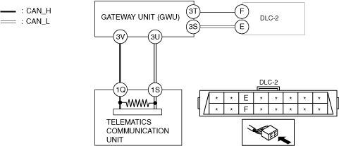
DETERMINING SHORT TO POWER SUPPLY LOCATION (CAN-BUS No.4) [TYPE-B (L.H.D.)]
id100270003100
System Wiring Diagram
ac5wzw00014754
|
Determination Procedure
|
Step |
Inspection |
Action |
|
|---|---|---|---|
|
1
|
INSPECT FOR SHORT TO POWER SUPPLY BETWEEN GATEWAY UNIT (GWU) AND DLC-2
• Switch the ignition off.
• Disconnect the negative battery cable.
• Disconnect the connector 3 which has gateway unit (GWU) terminals 3T and 3S.
• Connect the negative battery terminal.
• Switch the ignition ON (engine off).
• Measure the voltage at DLC-2 terminals F and E.
• Is the voltage 0 V?
|
Yes
|
Go to the next step.
|
|
No
|
Repair or replace the wiring harness between the DLC-2 and gateway unit (GWU) because the wiring harness is shorted to the power supply.
|
||
|
2
|
INSPECT CAN LINE BETWEEN GATEWAY UNIT (GWU) AND TELEMATICS COMMUNICATION UNIT FOR SHORT TO POWER SUPPLY
• Measure the voltage at gateway unit (GWU) terminals 3V and 3U (wiring harness side).
• Is the voltage between 1.5—3.5 V?
|
Yes
|
Replace the gateway unit (GWU) because there is a short to the power supply in the gateway unit (GWU).
|
|
No
|
Go to the next step.
|
||
|
3
|
INSPECT TELEMATICS COMMUNICATION UNIT FOR SHORT TO POWER SUPPLY
• Switch the ignition off.
• Disconnect the negative battery cable.
• Disconnect the telematics communication unit connector.
• Connect the connector 3 which has gateway unit (GWU) terminals 3V and 3U.
• Connect the negative battery cable.
• Switch the ignition ON (engine off).
• Measure the voltage at DLC-2 terminals F and E.
• Is the voltage between 1.5 — 3.5 V?
|
Yes
|
Replace the telematics communication unit because there is a short to the power supply in the telematics communication unit.
|
|
No
|
Repair or replace the wiring harness between the telematics communication unit and gateway unit (GWU) because the wiring harness is shorted to the power supply.
|
||