 |
acxaaw00000174
TRANSAXLE FLUID TEMPERATURE (TFT) SENSOR INSPECTION [AW6A-EL, AW6AX-EL]
id051723801000
On-Vehicle Inspection
1. Disconnect the negative battery cable.
2. Remove the air cleaner component. (See INTAKE-AIR SYSTEM REMOVAL/INSTALLATION [L3 Turbo].)
3. Remove the TCM. (See TCM REMOVAL/INSTALLATION [AW6A-EL, AW6AX-EL].)
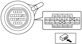
4. Verify that there is no continuity between coupler component terminals B7 and GND, or B8 and GND.
acxaaw00000174
|
5. Install the TCM. (See TCM REMOVAL/INSTALLATION [AW6A-EL, AW6AX-EL].)
6. Install the air cleaner component. (See INTAKE-AIR SYSTEM REMOVAL/INSTALLATION [L3 Turbo].)
7. Connect the negative battery cable.
Off-Vehicle Inspection
1. Disconnect the negative battery cable.
2. Remove the air cleaner component. (See INTAKE-AIR SYSTEM REMOVAL/INSTALLATION [L3 Turbo].)
3. Remove the under cover.
4. Drain the ATF. (See AUTOMATIC TRANSAXLE FLUID (ATF) REPLACEMENT [AW6A-EL, AW6AX-EL].)
5. Remove the resonance chamber. (See INTAKE-AIR SYSTEM REMOVAL/INSTALLATION [L3 Turbo].)
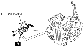
6. Remove the thermo valve. (See OIL COOLER REMOVAL/INSTALLATION [AW6A-EL, AW6AX-EL].)
acxaaw00000175
|
7. Remove the control valve body. (See CONTROL VALVE BODY REMOVAL/INSTALLATION [AW6A-EL, AW6AX-EL].)
8. Remove the TFT sensor. (See TRANSAXLE FLUID TEMPERATURE (TFT) SENSOR REMOVAL/INSTALLATION [AW6A-EL, AW6AX-EL].)
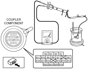
9. Place the TFT sensor and a thermometer in ATF as shown in the figure, and heat the ATF gradually.
acxaaw00000176
|
10. Measure the resistance between the coupler component terminals B7and B8.
Transaxle fluid temperature (TFT) sensor
|
ATF temperature (°C {°F}) |
Resistance (kilohm) |
|---|---|
|
10 {50}
|
5.62—7.31
|
|
25 {77}
|
Approx. 3.5
|
|
110 {230}
|
0.22—0.27
|
11. Install the TFT sensor. (See TRANSAXLE FLUID TEMPERATURE (TFT) SENSOR REMOVAL/INSTALLATION [AW6A-EL, AW6AX-EL].)
12. Install the control valve body. (See CONTROL VALVE BODY REMOVAL/INSTALLATION [AW6A-EL, AW6AX-EL].)
13. Install the thermo valve. (See OIL COOLER REMOVAL/INSTALLATION [AW6A-EL, AW6AX-EL].)
14. Install the resonance chamber. (See INTAKE-AIR SYSTEM REMOVAL/INSTALLATION [L3 Turbo].)
15. Add ATF to the specified level. (See AUTOMATIC TRANSAXLE FLUID (ATF) REPLACEMENT [AW6A-EL, AW6AX-EL].)
16. Install the under cover.
17. Install the air cleaner component. (See INTAKE-AIR SYSTEM REMOVAL/INSTALLATION [L3 Turbo].)
18. Connect the negative battery cable.