DTC U2300:00 [PCM (SKYACTIV-D 2.2)]
id0102j5228300
DTC U2300:00 |
Global central configuration error |
---|---|
DETECTION CONDITION
|
• No configuration of instrument cluster
• The configuration signal with the estimated CAN ID is not sent from the instrument cluster.
• The configuration signal value sent via CAN from the instrument cluster is unknown or invalid.
• The configuration signal value sent via CAN from the instrument cluster is a value other than the estimated value.
• The configuration signal value sent via CAN from the instrument cluster does not match the PCM value.
Diagnostic support note
• This is a continuous monitor (other).
• The check engine light does not illuminate.
• FREEZE FRAME DATA/Snapshot data is not available.
• DTC is not stored in the PCM memory.
|
FAIL-SAFE FUNCTION
|
Not applicable
|
POSSIBLE CAUSE
|
• CAN drive error (instrument cluster or PCM)
• Configuration data for the instrument cluster is incorrectly set
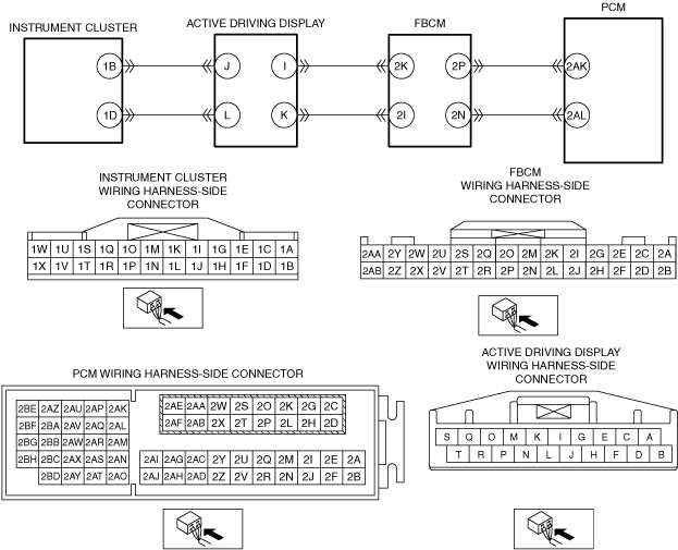
• Malfunction in CAN line between the instrument cluster and PCM
• Front body control module (FBCM) malfunction
• Active driving display malfunction
• PCM connector or terminal malfunction
• Instrument cluster connector or terminal malfunction
• Poor installation of instrument cluster
• Instrument cluster malfunction
• Error in non-volatile memory in PCM
• PCM malfunction
|
![]() |
Diagnostic Procedure
Step |
Inspection |
Results |
Action |
---|---|---|---|
1
|
VERIFY OTHER RELATED DTCs
• Switch the ignition OFF, and then switch it ON (engine off).
• Display the DTCs using the M-MDS.
• Has DTC U0155:00 been recorded?
|
Yes
|
Repair the malfunctioning location according to the applicable DTC troubleshooting.
|
No
|
Go to the next step.
|
||
2
|
VERIFY FRONT BODY CONTROL MODULE (FBCM) DTCs
• Perform the DTC inspection for the front body control module (FBCM) using the M-MDS.
• Is a DTC displayed?
|
Yes
|
Repair the malfunctioning location according to the applicable DTC troubleshooting.
|
No
|
Go to the next step.
|
||
3
|
VERIFY INSTRUMENT CLUSTER DTCs
• Perform the DTC inspection for the instrument cluster using the M-MDS.
• Is a DTC displayed?
|
Yes
|
Repair the malfunctioning location according to the applicable DTC troubleshooting.
|
No
|
Go to the next step.
|
||
4
|
VERIFY ACTIVE DRIVING DISPLAY DTCs
• Perform the active driving display DTC inspection using the M-MDS.
• Is a DTC displayed?
|
Yes
|
Repair the malfunctioning location according to the applicable DTC troubleshooting.
|
No
|
Go to the next step.
|
||
5
|
INSPECT INSTRUMENT CLUSTER CONNECTOR CONDITION
• Disconnect the instrument cluster connector.
• Inspect the connector engagement and connection condition, and inspect the terminals for damage, deformation, corrosion, or disconnection.
• Is the connector normal?
|
Yes
|
Go to the next step.
|
No
|
Repair or replace the connector, then go to Step 9.
|
||
6
|
VERIFY INSTRUMENT CLUSTER INSTALLATION CONDITION
• Verify that there is no looseness in the instrument cluster installation.
• Is the instrument cluster installation normal?
|
Yes
|
Go to the next step.
|
No
|
Install the instrument cluster correctly, then go to step 9.
|
||
7
|
INSPECT INSTRUMENT CLUSTER
• Inspect the instrument cluster.
• Is the instrument cluster normal?
|
Yes
|
Go to the next step.
|
No
|
Replace the instrument cluster, then go to step 9.
|
||
8
|
INSPECT PCM CONNECTOR CONDITION
• Disconnect the PCM connector.
• Inspect the connector engagement and connection condition, and inspect the terminals for damage, deformation, corrosion, or disconnection.
• Is the connector normal?
|
Yes
|
Repair or replace the following wiring harnesses.
• Instrument cluster terminal 1B and active driving display terminal J
• Instrument cluster terminal 1D and active driving display terminal L
• Active driving display terminal I and front body control module (FBCM) terminal 2K
• Active driving display terminal K and front body control module (FBCM) terminal 2I
• Front body control module (FBCM) terminal 2P and PCM terminal 2AK
• Front body control module (FBCM) terminal 2N and PCM terminal 2AL
Go to the next step.
|
No
|
Repair or replace the connector, then go to the next step.
|
||
9
|
VERIFY THAT REPAIRS HAVE BEEN COMPLETED
• Reconnect all the disconnected connectors.
• Refer to the [MEMORY CLEARING PROCEDURE] and clear the DTC.
• Switch the ignition ON (engine off) and wait for 15 s or more.
• Switch the ignition OFF.
• Wait until the main relay is off. (Approx. 1 min)
• Display the DTCs using the M-MDS.
• Has DTC U2300:00 been recorded?
|
Yes
|
Repeat the inspection from Step 1.
• If the malfunction recurs, replace the PCM, then go to the next step.
|
No
|
Go to the next step.
|
||
10
|
VERIFY OTHER DTCs
• Has any other DTC or pending code been stored?
|
Yes
|
Repair the malfunctioning location according to the applicable DTC troubleshooting.
|
No
|
DTC troubleshooting completed.
|