 |
ac8wzw00001285
TRANSFER REMOVAL/INSTALLATION [GW6AX-EL]
id0316g68006g3
1. Remove the propeller shaft. (See PROPELLER SHAFT REMOVAL/INSTALLATION.)
2. Remove the front crossmember component. (See FRONT CROSSMEMBER REMOVAL/INSTALLATION.)
3. Remove the front drive shaft (RH). (See FRONT DRIVE SHAFT REMOVAL/INSTALLATION.)
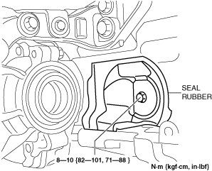
4. Remove the seal rubber.
ac8wzw00001285
|
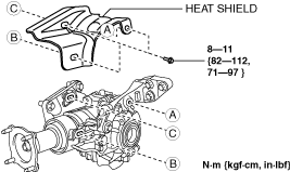
5. Remove the heat shield.
ac8wzw00001286
|
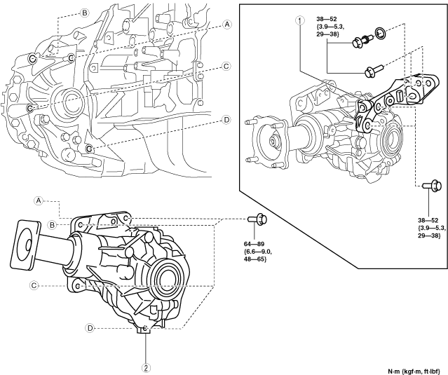
6. Remove in the order shown in the figure.
7. Install in the reverse order of removal.
8. After the engine and transaxle warms up, inspect for oil leakage and transfer operation.
ac8wzw00001287
|
|
1
|
Transfer bracket
|
|
2
|
Transfer
|
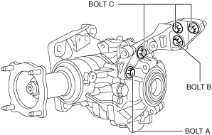
Transfer Bracket Installation Note
1. Install the transfer bracket to the transfer and temporarily tighten bolts A and B.
ac8wzw00001288
|
2. Completely tighten the bolts in the order of B and A.
3. Temporarily tighten bolts C.
4. Completely tighten bolts C.