 |
ac8wzw00001903
FRONT CROSSMEMBER REMOVAL/INSTALLATION
id021300801000
1. Remove the wheel and tire. (See WHEEL AND TIRE REMOVAL/INSTALLATION.)
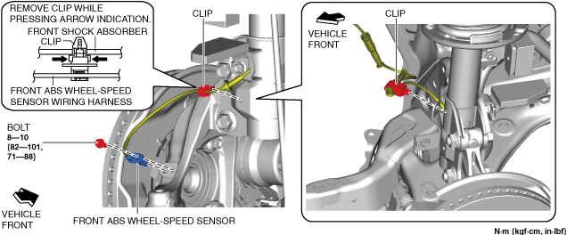
2. Disconnect the front ABS wheel-speed sensor wiring harness on the steering knuckle and set it aside so that it does not interfere with the servicing.
ac8wzw00001903
|
3. Remove the following parts.
4. Disconnect the tie-rod end from the steering knuckle. (See TIE-ROD END REPLACEMENT.)
5. Disconnect the front lower arm ball joint from the steering knuckle. (See FRONT LOWER ARM REMOVAL/INSTALLATION.)
6. Remove the screws shown in the figure and partially peel back the front mudguard.
ac8wzw00001904
|
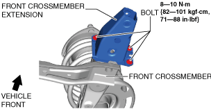
7. Disconnect the front crossmember extension.
ac8wzw00001905
|
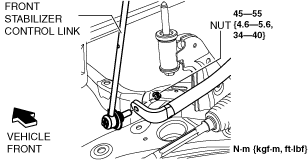
8. Disconnect the front stabilizer control link (front stabilizer side).
ac8wzw00001906
|
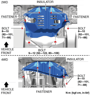
9. Remove the insulator. (See Insulator Installation Note.)
ac8wzw00001907
|
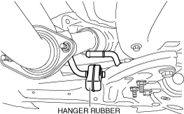
10. Disconnect the hanger rubber from the front crossmember and set it aside.
ac8wzw00001908
|
11. Remove the joint cover. (See STEERING WHEEL AND COLUMN REMOVAL/INSTALLATION.)
12. Disconnect the intermediate shaft from the steering gear and linkage. (See STEERING WHEEL AND COLUMN REMOVAL/INSTALLATION.)
13. Remove the bolts. (See No.1 Engine Mount Rubber Removal Note.) (See No.1 Engine Mount Rubber Installation Note.)
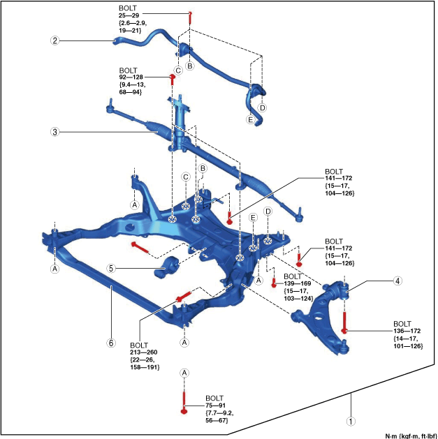
14. Remove in the order shown in the figure.
15. Install in the reverse order of removal. (See Suspension Links Installation Note.)
16. If the front crossmember is replaced, inspect the wheel alignment and adjust it if necessary. (See FRONT WHEEL ALIGNMENT.)
ac8wzw00001911
|
|
1
|
Front crossmember component
|
|
2
|
Front stabilizer component
(See FRONT STABILIZER REMOVAL.)
|
|
3
|
Steering gear and linkage
|
|
4
|
Front lower arm
|
|
5
|
No.1 engine mount rubber
|
|
6
|
Front crossmember
|
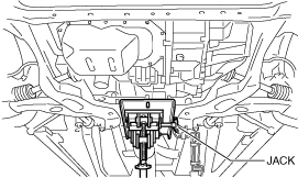
Front Crossmember Component Removal Note
1. Support the front crossmember component using a jack.
ac8wzw00001912
|
2. Remove the installation bolts of the front crossmember component.
3. Remove the front crossmember, front stabilizer, front lower arm, and the steering gear and linkage as a single unit.
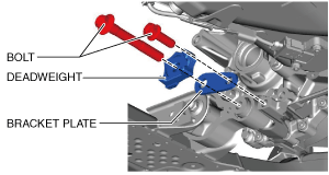
No.1 Engine Mount Rubber Removal Note
2WD
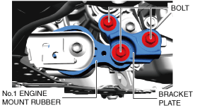
1. Remove the bracket plate.
ac8wzw00001909
|
4WD
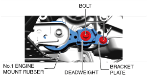
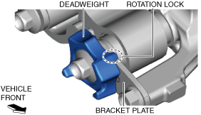
1. Remove the deadweight and bracket plate.
ac8wzw00001910
|
Suspension Links Installation Note
1. When installing the joint sections with rubber bushings, perform the following procedures.
Front Crossmember Component Installation Note
ac8wzw00001913
|
No.1 Engine Mount Rubber Installation Note
2WD
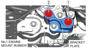
1. Install the No.1 engine mount rubber and the bracket plate and temporarily tighten the bolts shown in the figure.
ac8wzw00004168
|
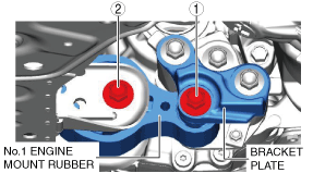
2. Tighten the bracket plate installation bolts in the order shown in the figure.
ac8wzw00001915
|
SKYACTIV-G 2.5
|
No. |
Tightening torque |
|---|---|
|
1
|
84—98 N·m {8.6—9.9 kgf·m, 62—72 ft·lbf}
|
|
2
|
84—98 N·m {8.6—9.9 kgf·m, 62—72 ft·lbf}
|
SKYACTIV-D 2.2
|
No. |
Tightening torque |
|---|---|
|
1
|
131—153 N·m {14—15 kgf·m, 97—112 ft·lbf}
|
|
2
|
131—153 N·m {14—15 kgf·m, 97—112 ft·lbf}
|
3. Tighten the No.1 engine mount rubber installation bolts in the order shown in the figure.
ac8wzw00001916
|
|
No. |
Tightening torque |
|---|---|
|
1
|
130—151 N·m {14—15 kgf·m, 96—111 ft·lbf}
|
|
2
|
130—164 N·m {14—16 kgf·m, 96—120 ft·lbf}
|
4WD
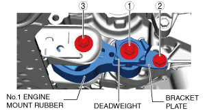
1. Install the No.1 engine mount rubber, bracket plate, and deadweight, and temporarily tighten the bolts shown in the figure.
ac8wzw00004169
|
ac8wzw00001918
|
2. Tighten the installation bolts for the No. 1 engine mount rubber, bracket plate, and deadweight in the order shown in the figure.
ac8wzw00001919
|
|
No. |
Tightening torque |
|---|---|
|
1
|
140—163 N·m {15—16 kgf·m, 104—120 ft·lbf}
|
|
2
|
55—69 N·m {5.7—7.0 kgf·m, 41—50 ft·lbf}
|
|
3
|
130—164 N·m {14—16 kgf·m, 96—120 ft·lbf}
|
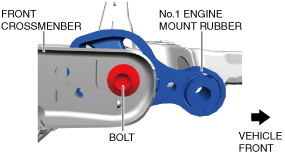
No.1 Engine Mount Rubber, Front Crossmember Installation Note
1. Temporarily tighten the bolt shown in the figure.
ac8wzw00004170
|
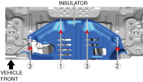
Insulator Installation Note
2WD
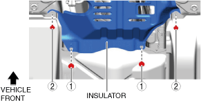
1. Install the fasteners in the order shown in the figure.
ac8wzw00001920
|
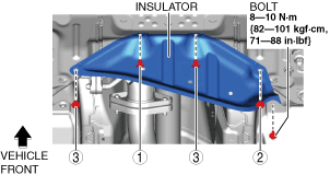
2. Install the bolts in the order shown in the figure.
ac8wzw00001921
|
|
No. |
Tightening torque |
|---|---|
|
1
|
9—12 N·m {92—122 kgf·cm, 80—106 in·lbf}
|
|
2
|
8—10 N·m {82—101 kgf·cm, 71—88 in·lbf}
|
4WD
1. Install the fasteners in the order shown in the figure.
ac8wzw00001922
|
2. Install the bolt.