 |
ac5wzw00009816
VACUUM PUMP REMOVAL/INSTALLATION [SKYACTIV-D 2.2]
id0411008036s8
Replacement part
|
O-ring
Quantity: 1
Location of use: Vacuum pump
|
Oil and chemical type
|
Silicone sealant
Type:TB1217D or equivalent
|
1. Disconnect the negative battery terminal. (See NEGATIVE BATTERY TERMINAL DISCONNECTION/CONNECTION.)
2. Remove the engine cover. (See ENGINE COVER REMOVAL/INSTALLATION [SKYACTIV-D 2.2].)
3. Remove the battery and the battery tray. (See BATTERY REMOVAL/INSTALLATION [SKYACTIV-D 2.2].)
4. Remove the following parts as a single unit. (See INTAKE-AIR SYSTEM REMOVAL/INSTALLATION [SKYACTIV-D 2.2].)
5. Disconnect the blow-by heater connector. (See INTAKE-AIR SYSTEM REMOVAL/INSTALLATION [SKYACTIV-D 2.2].)
6. Disconnect the breather hose from the cylinder head cover. (See INTAKE-AIR SYSTEM REMOVAL/INSTALLATION [SKYACTIV-D 2.2].)
7. Remove the turbocharger air inlet pipe and the breather hose as a single unit. (See INTAKE-AIR SYSTEM REMOVAL/INSTALLATION [SKYACTIV-D 2.2].)
8. Pinch open the clamp using pliers and disconnect the vacuum hose from the vacuum pump. (See VACUUM HOSE REMOVAL/INSTALLATION [SKYACTIV-D 2.2].)
9. Detach the clip.
ac5wzw00009816
|
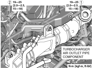
10. Remove the nuts and set the turbocharger air outlet pipe component aside. (See Turbocharger Air Outlet Pipe Component Installation Note.)
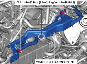
11. Remove the nuts and set the water pipe component aside.
ac5wzw00009817
|
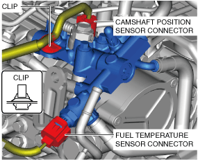
12. Disconnect the connector and clip shown in the figure.
ac5wzw00009818
|
13. Perform the “BEFORE SERVICE PRECAUTION”. (See BEFORE SERVICE PRECAUTION [SKYACTIV-D 2.2].)
14. Remove the following parts. (See SUPPLY PUMP DATA RESET [SKYACTIV-D 2.2].)
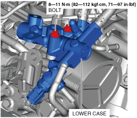
15. Remove the bolts and set the lower case aside.
ac5wzw00009819
|
16. Remove the insulator installation bolts. (See EGR PIPE REMOVAL/INSTALLATION [SKYACTIV-D 2.2].)
17. Set the insulator aside so that it does not interfere with the servicing for the vacuum pump removal.
18. Remove in the order shown in the figure.
19. Install in the reverse order of removal.
20. Refer to the “AFTER SERVICE PRECAUTION“ and perform the fuel hose installation procedure and fuel line air bleeding.(See BEFORE SERVICE PRECAUTION [SKYACTIV-D 2.2].)
am6zzw00008770
|
|
1
|
Vacuum tube
|
|
2
|
Bolt
|
|
3
|
Vacuum pump
(See Vacuum Pump Removal Note.)
|
|
4
|
O-ring
|
Vacuum Pump Removal Note
1. When removing the vacuum pump, set a cloth to the underside of the vacuum pump installation surface so that engine oil does not get on other parts.
2. Remove the vacuum pump.
Vacuum Pump, O-ring Installation Note
1. Drain the remaining engine oil in the vacuum pump by manually rotating the vacuum pump.
2. Remove any grease or dirt from the O-ring installation groove and installation surface.
3. Install a new O-ring to the vacuum pump.
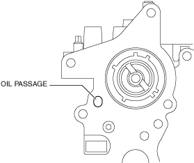
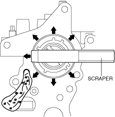
4. Insert a cloth into the oil passage shown in the figure.
am3zzw00017994
|
5. Scrape the cylinder head from the inside to the outside using a scraper and clean away the remaining silicone sealant on the cylinder head so that it does not get in the cylinder head.
am3zzw00017995
|
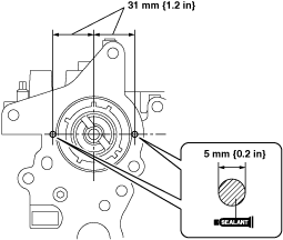
6. Clean the cylinder head.
7. Apply silicone sealant (TB1217D or equivalent) to the positions shown in the figure.
am6zzw00008493
|
8. Install the vacuum pump.
Turbocharger Air Outlet Pipe Component Installation Note
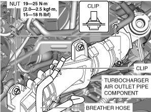
1. Install the nuts in the order shown in the figure.
ac5wzw00009820
|