DSC HU/CM REMOVAL/INSTALLATION [SKYACTIV-G 2.5]
id0415008010e1
Replacement part
|
Pipe holder
Quantity: 1
Location of use: Brake pipe
|
Oil and chemical type
|
Brake fluid
Type: SAE J1703 or FMVSS116 DOT-3
|
-
Warning
-
• If the DSC HU/CM configuration is not completed, it could result in an unexpected accident due to the DSC being inoperative. If the DSC HU/CM is replaced, always use the automatic configuration function so that the DSC operation conditions are correct.
• If the initialization of the sensors for DSC-related parts is not completed, the DSC will not operate normally which could lead to an unexpected accident. Therefore, if the DSC HU/CM is replaced or removed/installed, always perform the initialization of the sensors for DSC-related parts so that the DSC will operate normally.
-
Caution
-
• The internal parts of the DSC HU/CM could be damaged if dropped. Be careful not to drop the DSC HU/CM. Replace the DSC HU/CM if it is subjected to an impact.
• Be careful not to let brake fluid get on the paint surface. Otherwise, it could cause paint peeling. If brake fluid gets on the paint surface, wash and flush it off completely with water immediately.
-
Note
-
• When the ignition is switched ON after the DSC HU/CM has been replaced, the DSC CM reads data from the instrument cluster via CAN communication to perform automatic configuration.
• The DSC CM stores the vehicle specification information.
• A new DSC HU/CM stores the vehicle specification information.
• Tighten the brake pipe flare nut using a commercially available flare nut wrench.
1. Disconnect the negative battery terminal. (See NEGATIVE BATTERY TERMINAL DISCONNECTION/CONNECTION.)
2. Remove the washer tank bracket. (See WASHER TANK REMOVAL/INSTALLATION.)
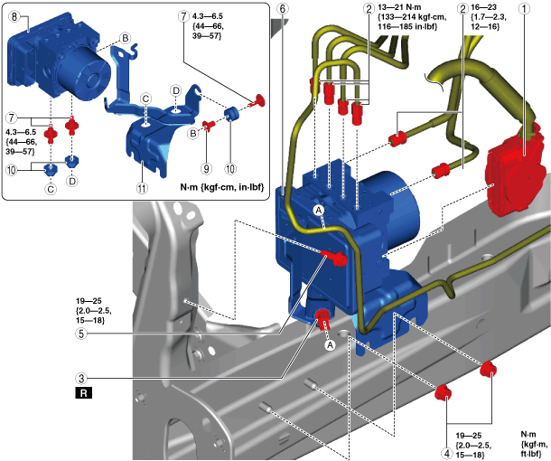
3. Remove in the order shown in the figure.
4. Install in the reverse order of removal.
5. After installation, add brake fluid and perform the air bleeding/fluid leakage inspection. (See BRAKE FLUID AIR BLEEDING.)
6. If the DSC HU/CM is replaced, perform the auto configuration and the initialization of the sensors for DSC-related parts using the following procedure.
- (1) Switch the ignition ON (engine off or on) and wait for 10 s or more.
-
- (2) Switch the ignition off and wait for 3 s or more.
-
- (3) Switch the ignition ON (engine off or on) and wait for 3 s or more for the DSC HU/CM auto configuration to complete.
-
- (4) Clear the DTC. (See CLEARING DTC [DYNAMIC STABILITY CONTROL (DSC)].)
-
- (5) Switch the ignition off and wait for 3 s or more.
-
- (6) Switch the ignition ON (engine off or on) and wait for 10 s or more.
-
- (7) Using the M-MDS, verify that DTCs U2101:00/U2300:52/U2300:54/U2300:55/U2300:56/U2300:64 are not displayed.
-
-
- (8) Perform the sensor initialization for the DSC-related parts. (See DSC RELATED PARTS SENSOR INITIALIZATION PROCEDURE.)
-
- (9) Clear the DTC. (See CLEARING DTC [DYNAMIC STABILITY CONTROL (DSC)].)
-
- (10) Switch the ignition off and wait for 3 s or more.
-
- (11) Switch the ignition ON (engine off or on) and wait for 10 s or more.
-
- (12) Using the M-MDS, verify that DTCs C0044:54/C0061:54/C0062:54/C0063:54 are not displayed.
-
-
|
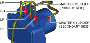
1
|
DSC HU/CM connector
|
|
2
|
Brake pipe
|
|
3
|
Pipe holder
|
|
4
|
Nut
|
|
5
|
Bolt
|
|
6
|
DSC HU/CM component
|
|
7
|
Bolt
|
|
8
|
DSC HU/CM
|
|
9
|
Spacer
|
|
10
|
Mount rubber
|
|
11
|
Bracket
|
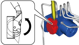
DSC HU/CM Connector Removal Note
-
Caution
-
• If sand or other foreign matter get into the connector, it may be difficult to remove. To prevent damaging the connector, be careful not to use excessive force removing the connector.
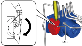
1. Move the lock lever in the direction of the arrow while pressing the lock lever tab.
2. Disconnect the connector.
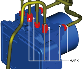
Brake Pipe Removal Note
1. Place alignment marks on the brake pipe and the DSC HU/CM.
2. Apply protective tape to the connector so that brake fluid does not get in the connector.
3. Remove the brake pipe.
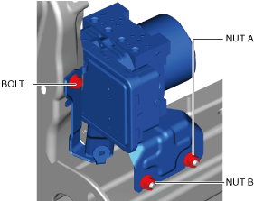
Bolt, Nut Installation Note
1. Tighten the bolt.
-
Tightening torque
-
19—25 N·m {2.0—2.5 kgf·m, 15—18 ft·lbf}
2. Tighten nut A.
-
Tightening torque
-
19—25 N·m {2.0—2.5 kgf·m, 15—18 ft·lbf}
3. Tighten nut B.
-
Tightening torque
-
19—25 N·m {2.0—2.5 kgf·m, 15—18 ft·lbf}
Brake Pipe Installation Note
1. Referring to the figure, install the brake pipe to the DSC HU/CM by aligning the marks which made before removing the brake pipe.
DSC HU/CM Connector Installation Note
1. Connect the connector and move the lock lever in the direction of the arrow.
2. After connecting the connector, verify that the lock lever is inserted completely.