System malfunction location
• B1C1C:12: Front airflow mode actuator (potentiometer) circuit short to power supply
• B1C1C:13: Front airflow mode actuator (potentiometer) circuit open
Detection condition
• Malfunction in wiring harness between front airflow mode actuator and front climate control unit
Fail-safe function
Malfunction determined when ignition switched ON
• Front airflow mode actuator drive signal is stopped right when the malfunction is determined.
-
― However, for manual operation using the MODE switch, vent or defroster mode is available.
Malfunction already exists when ignition switched ON
• Control based on ambient temperature.
-
― However, for manual operation using the MODE switch, vent or defroster mode is available.
Possible cause
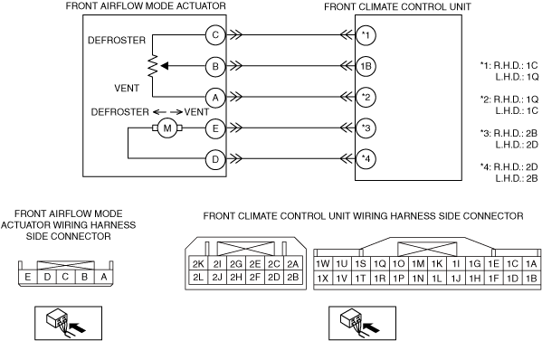
R.H.D.:
• Front airflow mode actuator connector or terminal malfunction
• Front airflow mode actuator malfunction
• Front climate control unit connector or terminal malfunction
• Front climate control unit malfunction
• Open circuit in wiring harness between the following terminals:
-
― Front climate control unit terminal 1C—front airflow mode actuator terminal C― Front climate control unit terminal 1B—front airflow mode actuator terminal B― Front climate control unit terminal 1Q—front airflow mode actuator terminal A
• Short to power supply in wiring harness between the following terminals:
-
― Front climate control unit terminal 1C—front airflow mode actuator terminal C― Front climate control unit terminal 1B—front airflow mode actuator terminal B― Front climate control unit terminal 1Q—front airflow mode actuator terminal A
Possible cause
L.H.D.:
• Front airflow mode actuator connector or terminal malfunction
• Front airflow mode actuator malfunction
• Front climate control unit connector or terminal malfunction
• Front climate control unit malfunction
• Open circuit in wiring harness between the following terminals:
-
― Front climate control unit terminal 1Q—front airflow mode actuator terminal C― Front climate control unit terminal 1B—front airflow mode actuator terminal B― Front climate control unit terminal 1C—front airflow mode actuator terminal A
• Short to power supply in wiring harness between the following terminals:
-
― Front climate control unit terminal 1Q—front airflow mode actuator terminal C― Front climate control unit terminal 1B—front airflow mode actuator terminal B― Front climate control unit terminal 1C—front airflow mode actuator terminal A