FRONT AIRFLOW MODE ACTUATOR INSPECTION
id074000804500
L.H.D.
1. Disconnect the negative battery terminal. (See NEGATIVE BATTERY TERMINAL DISCONNECTION/CONNECTION.)
2. Remove the following parts:
- (1) Console side panel (See CONSOLE SIDE PANEL REMOVAL/INSTALLATION.)
-
- (2) Selector lever knob (See SELECTOR LEVER COMPONENT REMOVAL/INSTALLATION.)
-
- (3) Shift panel (See SHIFT PANEL REMOVAL/INSTALLATION.)
-
- (4) Front console (See FRONT CONSOLE BOX REMOVAL/INSTALLATION.)
-
- (5) Glove compartment (See GLOVE COMPARTMENT REMOVAL/INSTALLATION.)
-
- (6) Dashboard under cover (See DASHBOARD UNDER COVER REMOVAL/INSTALLATION.)
-
- (7) Passenger-side decoration panel (See DECORATION PANEL REMOVAL/INSTALLATION.)
-
- (8) Front scuff plate (See FRONT SCUFF PLATE REMOVAL/INSTALLATION.)
-
- (9) Front side trim (See FRONT SIDE TRIM REMOVAL/INSTALLATION.)
-
- (10) Bonnet release lever (See BONNET RELEASE LEVER AND RELEASE CABLE REMOVAL/INSTALLATION.)
-
- (11) Fuel-filler lid opener lever (See FUEL-FILLER LID OPENER AND LEVER REMOVAL/INSTALLATION.)
-
- (12) Lower panel (See LOWER PANEL REMOVAL/INSTALLATION.)
-
- (13) Passenger-side front heat duct (See FRONT HEAT DUCT REMOVAL/INSTALLATION.)
-
3. Remove the front airflow mode actuator. (See FRONT AIRFLOW MODE ACTUATOR REMOVAL.)
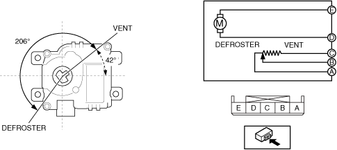
4. Apply battery positive voltage and connect the ground to the front airflow mode actuator terminals as indicated in the table below and verify the operation condition.
|
B+ Terminal
|
Ground Terminal
|
Operation
|
|
D
|
E
|
VENT → DEFROSTER
|
|
E
|
D
|
DEFROSTER → VENT
|
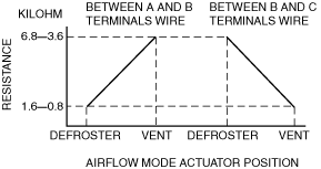
5. Verify that the resistance between terminals A and B, B and C matches the front airflow mode actuator operation as shown in the graph.
-
R.H.D.
1. Disconnect the negative battery terminal. (See NEGATIVE BATTERY TERMINAL DISCONNECTION/CONNECTION.)
2. Remove the following parts:
- (1) Console side panel (See CONSOLE SIDE PANEL REMOVAL/INSTALLATION.)
-
- (2) Selector lever knob (See SELECTOR LEVER COMPONENT REMOVAL/INSTALLATION.)
-
- (3) Shift panel (See SHIFT PANEL REMOVAL/INSTALLATION.)
-
- (4) Front console (See FRONT CONSOLE BOX REMOVAL/INSTALLATION.)
-
- (5) Glove compartment (See GLOVE COMPARTMENT REMOVAL/INSTALLATION.)
-
- (6) Dashboard under cover (See DASHBOARD UNDER COVER REMOVAL/INSTALLATION.)
-
- (7) Passenger-side decoration panel (See DECORATION PANEL REMOVAL/INSTALLATION.)
-
- (8) Front scuff plate (See FRONT SCUFF PLATE REMOVAL/INSTALLATION.)
-
- (9) Front side trim (See FRONT SIDE TRIM REMOVAL/INSTALLATION.)
-
- (10) Bonnet release lever (See BONNET RELEASE LEVER AND RELEASE CABLE REMOVAL/INSTALLATION.)
-
- (11) Fuel-filler lid opener lever (See FUEL-FILLER LID OPENER AND LEVER REMOVAL/INSTALLATION.)
-
- (12) Lower panel (See LOWER PANEL REMOVAL/INSTALLATION.)
-
- (13) Passenger-side front heat duct (See FRONT HEAT DUCT REMOVAL/INSTALLATION.)
-
3. Remove the front airflow mode actuator. (See FRONT AIRFLOW MODE ACTUATOR REMOVAL.)
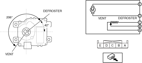
4. Apply battery positive voltage and connect the ground to the front airflow mode actuator terminals as indicated in the table below and verify the operation condition.
|
B+ Terminal
|
Ground Terminal
|
Operation
|
|
D
|
E
|
DEFROSTER → VENT
|
|
E
|
D
|
VENT → DEFROSTER
|
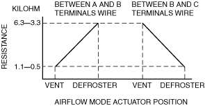
5. Verify that the resistance between terminals A and B, B and C matches the front airflow mode actuator operation as shown in the graph.
-