Note
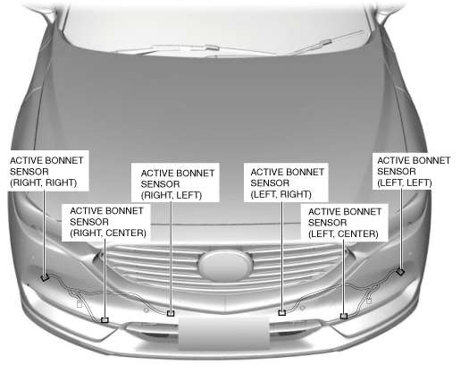
• The active bonnet sensors are installed in the following positions.
ac8wzw00000278
|
ACTIVE BONNET SENSOR REMOVAL/INSTALLATION
id081300000700
ac8wzw00000278
|
Active Bonnet Sensor (Left, Left)
1. Switch the ignition off.
2. Disconnect the negative battery terminal and wait for 1 min or more. (See NEGATIVE BATTERY TERMINAL DISCONNECTION/CONNECTION.)
3. Lift up the vehicle.
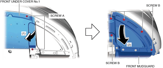
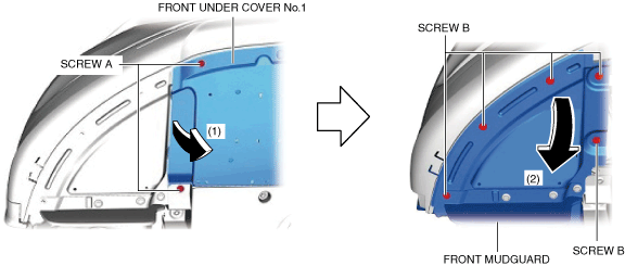
4. Remove the screws A.
ac8wzw00000279
|
5. Bend back the front under cover No.1 in the direction of the arrow (1) shown in the figure.
6. Remove the screws B.
7. Bend back the front mud guard in the direction of the arrow (2) shown in the figure.
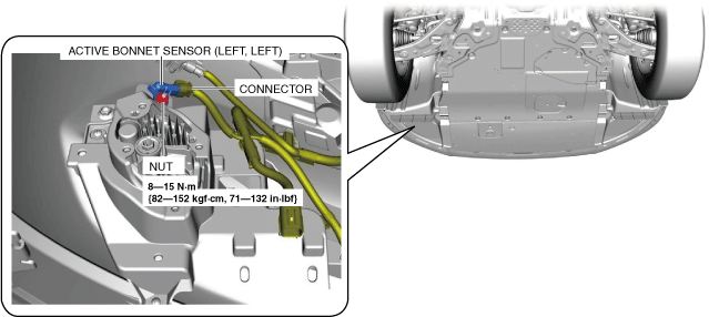
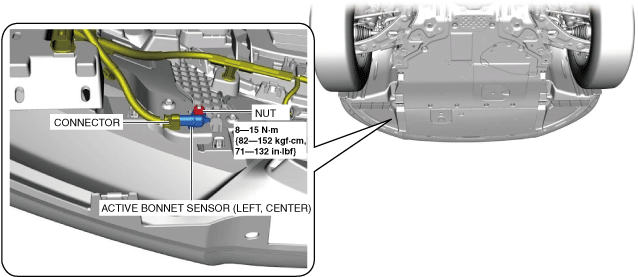
8. Disconnect the connector. (See Connector disconnect note.)
ac8wzw00000280
|
9. Remove the nut.
10. Remove the active bonnet sensor.
11. Install in the reverse order of removal.
12. Switch the ignition ON (engine off or on).
13. Verify that the active bonnet warning light illuminates for approx. 6 s and turns off.
Connector disconnect note
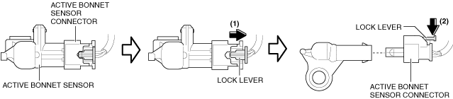
1. Pull out the connector lock lever in the direction of arrow (1) shown in the figure.
ac8wzw00000281
|
2. While pressing the lock lever in the direction of arrow (2) shown in the figure, disconnect the connector.
Active Bonnet Sensor (Left, Center)
1. Switch the ignition off.
2. Disconnect the negative battery terminal and wait for 1 min or more. (See NEGATIVE BATTERY TERMINAL DISCONNECTION/CONNECTION.)
3. Lift up the vehicle.
4. Remove the screws A.
ac8wzw00000279
|
5. Bend back the front under cover No.1 in the direction of the arrow (1) shown in the figure.
6. Remove the screws B.
7. Bend back the front mud guard in the direction of the arrow (2) shown in the figure.
8. Disconnect the connector. (See Connector disconnect note.)
ac8wzw00000282
|
9. Remove the nut.
10. Remove the active bonnet sensor.
11. Install in the reverse order of removal.
12. Switch the ignition ON (engine off or on).
13. Verify that the active bonnet warning light illuminates for approx. 6 s and turns off.
Connector disconnect note
1. Pull out the connector lock lever in the direction of arrow (1) shown in the figure.
ac8wzw00000281
|
2. While pressing the lock lever in the direction of arrow (2) shown in the figure, disconnect the connector.
Active Bonnet Sensor (Left, Right)
1. Switch the ignition off.
2. Disconnect the negative battery terminal and wait for 1 min or more. (See NEGATIVE BATTERY TERMINAL DISCONNECTION/CONNECTION.)
3. Remove the seal board upper. (See SEAL BOARD UPPER REMOVAL/INSTALLATION.)
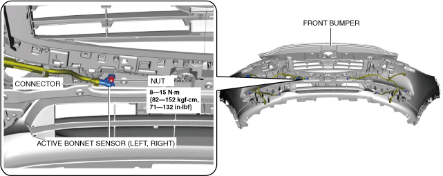
4. Remove the front bumper. (See FRONT BUMPER REMOVAL/INSTALLATION.)
5. Disconnect the connector. (See connector disconnect note.)
ac8wzw00000283
|
6. Remove the nut.
7. Remove the active bonnet sensor.
8. Install in the reverse order of removal.
9. Switch the ignition ON (engine off or on).
10. Verify that the active bonnet warning light illuminates for approx. 6 s and turns off.
11. Perform the 360°view monitor system aiming. (With 360° view monitor system) (See 360°VIEW MONITOR SYSTEM AIMING.)
connector disconnect note
1. Pull out the connector lock lever in the direction of arrow (1) shown in the figure.
ac8wzw00000281
|
2. While pressing the lock lever in the direction of arrow (2) shown in the figure, disconnect the connector.
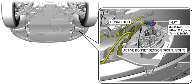
Active Bonnet Sensor (Right, Right)
1. Switch the ignition off.
2. Disconnect the negative battery terminal and wait for 1 min or more. (See NEGATIVE BATTERY TERMINAL DISCONNECTION/CONNECTION.)
3. Lift up the vehicle.
4. Remove the screws A.
ac8wzw00000284
|
5. Bend back the front under cover No.1 in the direction of the arrow (1) shown in the figure.
6. Remove the screws B.
7. Bend back the front mud guard in the direction of the arrow (2) shown in the figure.
8. Disconnect the connector. (See Connector disconnect note.)
ac8wzw00000285
|
9. Remove the nut.
10. Remove the active bonnet sensor.
11. Install in the reverse order of removal.
12. Switch the ignition ON (engine off or on).
13. Verify that the active bonnet warning light illuminates for approx. 6 s and turns off.
Connector disconnect note
1. Pull out the connector lock lever in the direction of arrow (1) shown in the figure.
ac8wzw00000281
|
2. While pressing the lock lever in the direction of arrow (2) shown in the figure, disconnect the connector.
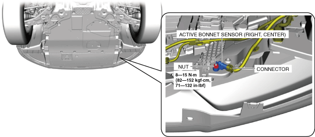
Active Bonnet Sensor (Right, Center)
1. Switch the ignition off.
2. Disconnect the negative battery terminal and wait for 1 min or more. (See NEGATIVE BATTERY TERMINAL DISCONNECTION/CONNECTION.)
3. Lift up the vehicle.
4. Remove the screws A.
ac8wzw00000284
|
5. Bend back the front under cover No.1 in the direction of the arrow (1) shown in the figure.
6. Remove the screws B.
7. Bend back the front mud guard in the direction of the arrow (2) shown in the figure.
8. Disconnect the connector. (See Connector disconnect note.)
ac8wzw00000286
|
9. Remove the nut.
10. Remove the active bonnet sensor.
11. Install in the reverse order of removal.
12. Switch the ignition ON (engine off or on).
13. Verify that the active bonnet warning light illuminates for approx. 6 s and turns off.
Connector disconnect note
1. Pull out the connector lock lever in the direction of arrow (1) shown in the figure.
ac8wzw00000281
|
2. While pressing the lock lever in the direction of arrow (2) shown in the figure, disconnect the connector.
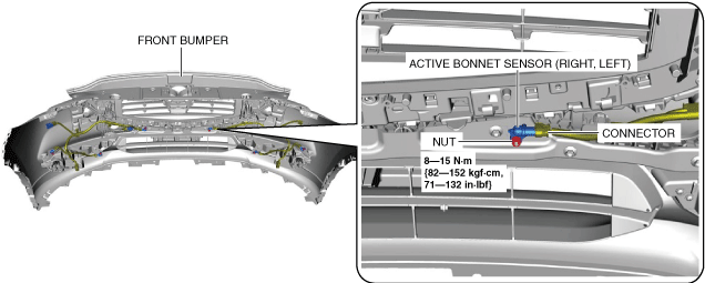
Active Bonnet Sensor (Right, Left)
1. Switch the ignition off.
2. Disconnect the negative battery terminal and wait for 1 min or more. (See NEGATIVE BATTERY TERMINAL DISCONNECTION/CONNECTION.)
3. Remove the seal board upper. (See SEAL BOARD UPPER REMOVAL/INSTALLATION.)
4. Remove the front bumper. (See FRONT BUMPER REMOVAL/INSTALLATION.)
5. Disconnect the connector. (See Connector disconnect note.)
ac8wzw00000287
|
6. Remove the nut.
7. Remove the active bonnet sensor.
8. Install in the reverse order of removal.
9. Switch the ignition ON (engine off or on).
10. Verify that the active bonnet warning light illuminates for approx. 6 s and turns off.
11. Perform the 360°view monitor system aiming. (With 360° view monitor system) (See 360°VIEW MONITOR SYSTEM AIMING.)
Connector disconnect note
1. Pull out the connector lock lever in the direction of arrow (1) shown in the figure.
ac8wzw00000281
|
2. While pressing the lock lever in the direction of arrow (2) shown in the figure, disconnect the connector.