|
1
|
VERIFY FREEZE FRAME DATA HAS BEEN RECORDED
• Has FREEZE FRAME DATA been recorded?
|
Yes
|
Go to the next step.
|
|
No
|
Record FREEZE FRAME DATA on the repair order, then go to the next step.
|
|
2
|
VERIFY RELATED SERVICE INFORMATION AVAILABILITY
• Verify related Service Information availability.
• Is any related Service Information available?
|
Yes
|
Perform repair or diagnosis according to the available Service Information.
• If the vehicle is not repaired, go to the next step.
|
|
No
|
Go to the next step.
|
|
3
|
INSPECT FOR SOURCE OF POTENTIAL HO2S CONTAMINATION
• Investigate the following items as potential sources of HO2S contamination:
-
― Use of unapproved silicon sealers
― Fuel contaminated by silicon additives
― Excessive oil consumption
― Glycol leaking internally in the engine
― Lead-contaminated fuel
― Short drive cycles in cold weather
― Use of unapproved cleaning agents
• Is a concern present?
|
Yes
|
Repair the source of the contamination. Change the engine oil and oil filter. Then go to Step12.
|
|
No
|
Go to the next step.
|
|
4
|
VISUALLY INSPECT HO2S WIRING HARNESS
• Connect the PCM connector.
• Visually inspect the HO2S wiring harness for exposed wiring water contamination, corrosion, and proper assembly.
• Is a concern present?
|
Yes
|
Repair or replace suspected part, then go to Step 12.
|
|
No
|
Go to the next step.
|
|
5
|
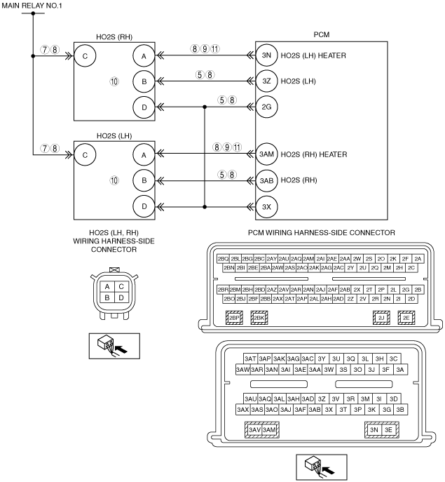
INSPECT HO2S AND SIGNAL RETURN CIRCUIT FOR OPEN CIRCUIT IN WIRING HARNESS
• Turn the ignition switch off.
• Disconnect suspect HO2S and PCM connectors.
• Measure the resistance between the following terminals (wiring harness-side):
-
― P0141:00:
-
• HO2S (RH) terminal B—PCM terminal 3Z
• HO2S (RH) terminal D—PCM terminal 2G
― P0161:00:
-
• HO2S (LH) terminal B—PCM terminal 3AB
• HO2S (LH) terminal D—PCM terminal 2G
• Is the resistance less than 5.0 ohms?
|
Yes
|
Go to the next step.
|
|
No
|
Repair or replace suspected part, Go to Step 12.
|
|
6
|
PERFORM KOEO SELF-TEST
• Reconnect suspect HO2S and PCM connectors.
• Perform the KOEO self-test.
• Are DTCs P0141:00, or P0161:00 present?
|
Yes
|
Go to the next step.
|
|
No
|
Go to Step 8.
|
|
7
|
INSPECT POWER SUPPLY IN WIRING HARNESS
• Turn the ignition switch off.
• Disconnect suspect HO2S and PCM connectors.
• Turn the ignition switch to the ON position (engine off).
• Measure the voltage between suspect HO2S connector terminal C and ground, on the wiring harness side.
• Is the voltage more than 10 V?
|
Yes
|
Go to the next step.
|
|
No
|
Inspect the ENG BAR fuse.
• If the is fuse deterioration, replace the fuse.
• If the fuse has melted, repair for short to ground and replace the fuse.
• If the fuse is normal, repair for an open circuit.
Go to Step 12.
|
|
8
|
INSPECT HO2S HEATER FOR SHORT IN WIRING HARNESS
• Turn the ignition switch off.
• Disconnect suspect HO2S and PCM connectors.
• Measure the resistance between HO2S wiring harness-side connector terminal A and the following terminals:
-
― HO2S wiring harness-side connector terminal C
― HO2S wiring harness-side connector terminal B
― HO2S wiring harness-side connector terminal D
• Are the resistances more than 10 kilohms?
|
Yes
|
Go to the next step.
|
|
No
|
Repair or replace suspected part, Go to Step 12.
|
|
9
|
INSPECT HO2S HEATER CIRCUIT FOR OPEN IN HARNESS
• Suspect HO2S and PCM connectors are disconnected.
• Measure the resistance between the following terminals (wiring harness-side):
-
― P0141:00:
-
• HO2S (RH) terminal A—PCM terminal 3N
― P0161:00:
-
• HO2S (LH) terminal A—PCM terminal 3AM
• Are the resistances less than 5 ohms?
|
Yes
|
Go to the next step.
|
|
No
|
Repair for open circuit. Go to Step 12.
|
|
10
|
INSPECT INTERNAL RESISTANCE OF HO2S HEATER
• Suspect HO2S and PCM connectors are disconnected.
• Measure the resistance between the suspect HO2S terminal A and C, on the component side.
• Is the resistance between 2—50 ohms?
|
Yes
|
Go to the next step.
(The system is normal at this time. The concern may have been caused by a loose or corroded connector.)
|
|
No
|
Replace HO2S.
Go to Step 12.
|
|
11
|
INSPECT HO2S HEATER FOR SHORT TO GROUND
• Suspect HO2S and PCM connectors are disconnected.
• Measure the resistance between HO2S terminal A on the wiring harness side and body ground.
• Is the resistance more than 10 kilohms?
|
Yes
|
Go to the next step.
|
|
No
|
Repair or replace suspected part, Go to the next step.
|
|
12
|
VERIFY TROUBLESHOOTING OF DTCs P0141:00, P0161:00 HAS BEEN COMPLETED
• Verify that all disconnected connectors are reconnected.
• Clear the DTC from the PCM memory using the M-MDS.
• Perform the KOEO or KOER self-test.
• Is the PENDING CODE for this DTC present?
|
Yes
|
Repeat the inspection from Step 1.
• If the malfunction recurs, replace the PCM.
Go to the next step.
|
|
No
|
Go to the next step.
|
|
13
|
VERIFY AFTER REPAIR PROCEDURE
• Perform the “AFTER REPAIR PROCEDURE”.
• Are any DTCs present?
|
Yes
|
Go to the applicable DTC inspection.
|
|
No
|
Troubleshooting completed.
|