|
1
|
VERIFY FREEZE FRAME DATA HAS BEEN RECORDED
• Has FREEZE FRAME DATA been recorded?
|
Yes
|
Go to the next step.
|
|
No
|
Record FREEZE FRAME DATA on the repair order, then go to the next step.
|
|
2
|
VERIFY RELATED SERVICE INFORMATION AVAILABILITY
• Verify related Service Information availability.
• Is any related Service Information available?
|
Yes
|
Perform repair or diagnosis according to the available Service Information.
• If the vehicle is not repaired, go to the next step.
|
|
No
|
Go to the next step.
|
|
3
|
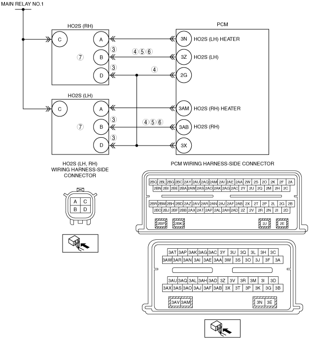
VISUALLY INSPECT HO2S AND PCM WIRING HARNESS
-
Note
-
• Disconnect the HO2S wiring harness connector. Only the suspect HO2S needs to be diagnosed.
• Turn the ignition switch off.
• Disconnect the suspect HO2S and PCM connectors.
• Visually inspect the HO2S wiring harness.
-
― Check the connector (both halves) for contamination
― Make sure the connector pins are fully seated
• Is a concern present?
|
Yes
|
Repair if necessary. Go to Step 8.
|
|
No
|
Go to the next step.
|
|
4
|
CHECK HO2S CIRCUIT(S) FOR OPEN IN HARNESS
-
Note
-
• Diagnose the suspect sensor indicated by the DTC.
• Verify the harness pins are in the correct location.
• Suspect HO2S and PCM connectors are disconnected.
• Turn the ignition switch off.
• Measure the resistance between the following terminals (wiring harness-side):
-
― P0137:00:
-
• HO2S (RH) terminal B—PCM terminal 3Z
• HO2S (RH) terminal D—PCM terminal 2G
― P0157:00:
-
• HO2S (LH) terminal B—PCM terminal 3AB
• HO2S (LH) terminal D—PCM terminal 2G
• Is the resistance less than 5 ohm?
|
Yes
|
Go to the next step.
|
|
No
|
Repair for open circuit, then go to Step 8.
|
|
5
|
CHECK HO2S CIRCUIT FOR SHORT TO GROUND
• Suspect HO2S and PCM connectors are disconnected.
• Measure the resistance between the following suspect HO2S terminals:
-
― P0137:00:
-
• HO2S (RH) terminals B and D (wiring harness-side)
• HO2S (RH) terminal B (wiring harness-side) and body ground
― P0157:00:
-
• HO2S (LH) terminals B and D (wiring harness-side)
• HO2S (LH) terminal B (wiring harness-side) and body ground
• Is the resistance greater than 10 kilohms?
|
Yes
|
Go to the next step.
|
|
No
|
Repair for short circuit, then go to Step 8.
|
|
6
|
CHECK HO2S CIRCUIT FOR SHORT TO POWER SUPPLY IN WIRING HARNESS
• Suspect HO2S and PCM connectors are disconnected.
• Turn the ignition switch to the ON position (engine off).
• Measure the voltage between the following suspect HO2S terminals (wiring harness-side) and body ground:
-
― HO2S (RH) terminal B (P0137:00)
― HO2S (LH) terminal B (P0157:00)
• Is any voltage present?
|
Yes
|
Repair for short circuit, then go to Step 8.
|
|
No
|
Go to the next step.
|
|
7
|
CHECK HO2S CIRCUIT CONTINUITY
-
Note
-
• HO2S is displayed as HO2S on the scan tool.
• Suspect HO2S and PCM connectors are disconnected.
• Turn the ignition switch off.
• Connect the PCM connector.
• Connect a 5 A fused jumper wire between suspect HO2S terminals (wiring harness-side) B and C
• Start the engine and run it at idle.
• Access the PCM and monitor the suspect HO2S signal PID (VOLT).
• Is the voltage greater than 1 V?
|
Yes
|
Replace the HO2S, then go to the next step.
|
|
No
|
Go to the next step.
(The system is operating normal at this time. The concern may have been caused by a loose or corroded connector.)
|
|
8
|
VERIFY TROUBLESHOOTING OF DTC P0137:00, P0157:00 HAS BEEN COMPLETED
• Verify that all disconnected connectors are reconnected.
• Clear the DTC from the PCM memory using the M-MDS.
• Perform the KOER self-test.
• Is the PENDING CODE for this DTC present?
|
Yes
|
Repeat the inspection from Step 1.
• If the malfunction recurs, replace the PCM.
Go to the next step.
|
|
No
|
Go to the next step.
|
|
9
|
VERIFY AFTER REPAIR PROCEDURE
• Perform the “AFTER REPAIR PROCEDURE”.
• Are any DTCs present?
|
Yes
|
Go to the applicable DTC inspection.
|
|
No
|
Troubleshooting completed.
|