ac9wzw00002248
|
COMPRESSION INSPECTION [MZI-3.7]
id0110c5800300
1. Verify that the battery is fully charged.
2. Warm up the engine to the normal operating temperature.
3. Perform “Fuel Line Safety Procedure”. Leave the fuel pump relay removed. (See BEFORE SERVICE PRECAUTION [MZI-3.7].)
4. Remove the engine cover. (See ENGINE COVER REMOVAL/INSTALLATION [MZI-3.7].)
5. Remove the dynamic chamber and throttle body as a single unit. (See INTAKE-AIR SYSTEM REMOVAL/INSTALLATION [MZI-3.7].)
6. Remove the ignition coils. (See IGNITION COIL REMOVAL/INSTALLATION [MZI-3.7].)
7. Remove the spark plugs.
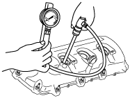
8. Measure the compression pressure using the following procedure.
ac9wzw00002248
|
Compression Pressure Limit Chart
|
Maximum pressure |
Minimum pressure |
Maximum pressure |
Minimum pressure |
Maximum pressure |
Minimum pressure |
Maximum pressure |
Minimum pressure |
|---|---|---|---|---|---|---|---|
|
924
{9.41, 134}
|
696
{7.10, 101}
|
1,131
{11.52, 164}
|
848
{8.65, 123}
|
1,338
{13.63, 194}
|
1,000
{10.20, 146}
|
1,544
{15.73, 224}
|
1,158
{11.81, 168}
|
|
938
{9.56, 136}
|
703
{7.17, 102}
|
1,145
{11.67, 166}
|
855
{8.72, 124}
|
1,351
{13.77, 196}
|
1,014
{10.34, 147}
|
1,558
{15.88, 226}
|
1,165
{11.88, 169}
|
|
952
{9.70, 138}
|
717
{7.31, 104}
|
1,158
{11.80, 168}
|
869
{8.86, 126}
|
1,365
{13.91, 198}
|
1,020
{10.40, 148}
|
1,572
{16.02, 228}
|
1,179
{12.02, 171}
|
|
965
{9.83, 140}
|
724
{7.38, 106}
|
1,172
{11.94, 170}
|
876
{8.93, 127}
|
1,379
{14.05, 200}
|
1,034
{10.54, 150}
|
1,586
{16.16, 230}
|
1,186
{12.09, 172}
|
|
979
{9.97, 142}
|
738
{7.53, 107}
|
1,186
{12.08, 172}
|
889
{9.07, 129}
|
1,303
{13.28, 202}
|
1,041
{10.62, 151}
|
1,600
{16.30, 232}
|
1,200
{12.24, 174}
|
|
933
{9.51, 144}
|
745
{7.60, 109}
|
1,200
{12.23, 174}
|
903
{9.21, 131}
|
1,407
{14.34, 204}
|
1,055
{10.76, 153}
|
1,055
{10.75, 153}
|
1,207
{12.31, 175}
|
|
1,007
{10.26, 146}
|
758
{7.73, 110}
|
1,214
{12.37, 176}
|
910
{9.28, 132}
|
1,420
{14.47, 206}
|
1,062
{10.83, 154}
|
1,627
{16.58, 154}
|
1,220
{12.44, 177}
|
|
1,020
{10.39, 148}
|
765
{7.80, 111}
|
1,227
{12.50, 178}
|
917
{9.35, 133}
|
1,434
{14.61, 208}
|
1,075
{10.96, 156}
|
1,641
{16.72, 238}
|
1,227
{12.51, 178}
|
|
1,034
{10.54, 150}
|
779
{7.94, 113}
|
1,241
{12.65, 180}
|
931
{9.49, 135}
|
1,448
{14.76, 210}
|
1,083
{10.04, 157}
|
1,655
{16.87, 240}
|
1,241
{12.65, 180}
|
|
1,048
{10.68, 152}
|
786
{8.02, 114}
|
1,255
{12.79, 182}
|
936
{9.54, 136}
|
1,462
{14.90, 212}
|
1,089
{11.10, 158}
|
1,669
{17.01, 242}
|
1,248
{12.73, 181}
|
|
1,062
{10.82, 154}
|
793
{8.09, 115}
|
1,269
{12.93, 184}
|
952
{9.70, 138}
|
1,476
{15.04, 214}
|
1,103
{11.25, 160}
|
1,682
{17.14, 244}
|
1,262
{12.87, 183}
|
|
1,076
{10.96, 156}
|
807
{8.23, 117,}
|
1,282
{13.06, 186}
|
965
{9.84, 140}
|
1,489
{15.17, 216}
|
1,117
{11.39, 162}
|
1,696
{17.28, 246}
|
1,269
{12.94, 184}
|
|
1,089
{11.10, 158}
|
814
{8.30, 118}
|
1,296
{13.21, 188}
|
972
{9.91, 141}
|
1,503
{15.32, 218}
|
1,124
{11.46, 163}
|
1,710
{17.43, 248}
|
1,202
{12.26, 186}
|
|
1,103
{11.24, 160}
|
827
{8.43, 120}
|
1,310
{13.35, 190}
|
979
{9.98, 142}
|
1,517
{15.46, 220}
|
1,138
{11.60, 165}
|
1,724
{17.57, 250}
|
1,289
{13.14, 187}
|
|
1,110
{11.31, 161}
|
834
{8.50, 121}
|
1,324
{13.49, 192}
|
993
{10.2, 144}
|
1,631
{16.62, 222}
|
1,145
{11.67, 166}
|
—
|
—
|
9. Remove the compression gauge.
10. Install the spark plugs. (See SPARK PLUG REMOVAL/INSTALLATION [MZI-3.7].)
11. Install the ignition coils. (See IGNITION COIL REMOVAL/INSTALLATION [MZI-3.7].)
12. Install the dynamic chamber and throttle body as a single unit. (See INTAKE-AIR SYSTEM REMOVAL/INSTALLATION [MZI-3.7].)
13. Install the engine cover. (See ENGINE COVER REMOVAL/INSTALLATION [MZI-3.7].)
14. Install the fuel pump relay.
15. Complete the “AFTER REPAIR PROCEDURE”. (See AFTER SERVICE PRECAUTION [MZI-3.7].)