 |
ac9wzw00003276
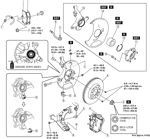
WHEEL HUB, STEERING KNUCKLE REMOVAL/INSTALLATION
id031100800400
1. Remove the front ABS wheel-speed sensor. (See FRONT ABS WHEEL-SPEED SENSOR REMOVAL/INSTALLATION.)
2. Remove in the order indicated in the table.
3. Install in the reverse order of removal.
4. After installation, inspect the front wheel alignment and adjust it if necessary. (See FRONT WHEEL ALIGNMENT.)
ac9wzw00003276
|
|
1
|
Brake hose clip
|
|
2
|
Locknut (crimped-fix type)/Locknut (self-lock type)
|
|
3
|
Brake caliper component
(See Brake Caliper Removal Note.)
|
|
4
|
Disc plate
|
|
5
|
Stabilizer control link (lower side)
|
|
6
|
Tie-rod end ball joint
|
|
7
|
Nut (front shock absorber lower side)
|
|
8
|
Front lower arm ball joint
|
|
9
|
Wheel hub, steering knuckle component
|
|
10
|
Spacer (With spacer)
|
|
11
|
Wheel hub
(See Wheel Hub Removal Note.)
(See Wheel Hub Installation Note.)
|
|
12
|
Retaining ring
|
|
13
|
Wheel bearing
(See Wheel Bearing Removal Note.)
|
|
14
|
Dust cover
(See Dust Cover Removal Note.)
(See Dust Cover Installation Note.)
|
|
15
|
Steering knuckle
|
|
16
|
Wheel hub bolt
(See Wheel Hub Bolt Removal Note.)
|
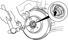
Locknut (Crimped-fix Type) Removal Note
1. Knock the crimped portion of the locknut outward using a small chisel and a hammer.
ac9uuw00001756
|
2. Lock the hub by applying the brakes.
3. Remove the locknut.
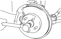
4. Install a spare nut onto the drive shaft so that the nut is flush with the end of the drive shaft.
5. Tap the nut with a copper hammer to loosen the drive shaft from the front wheel hub.
ac9uuw00001757
|
6. Separate the drive shaft from the wheel hub.
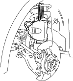
Brake Caliper Removal Note
1. Remove the brake caliper component from the steering knuckle and suspend it out of the way using a cable.
ac9uuw00001758
|
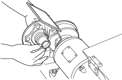
Wheel Hub Removal Note
1. Remove the wheel hub using the SSTs.
ac9uuw00001759
|
2. If the bearing inner race remains on the front wheel hub component, grind a section of the bearing inner race until approx. 0.5 mm {0.02 in} remains. Then remove it using a chisel.
acxjjw00001127
|
Wheel Bearing Removal Note
1. Remove the wheel bearing using the SSTs.
ac9uuw00001761
|
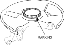
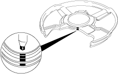
Dust Cover Removal Note
1. Mark the dust cover and steering knuckle for proper installation.
ac9uuw00001762
|
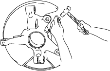
2. Remove the dust cover using a chisel.
ac9uuw00001763
|
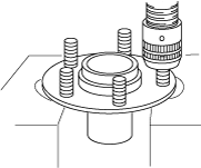
Wheel Hub Bolt Removal Note
1. Remove the hub bolt using a press.
ac9uuw00001764
|
Wheel Hub Bolt Installation Note
1. Install the new hub bolt using a press.
acxjjw00001128
|
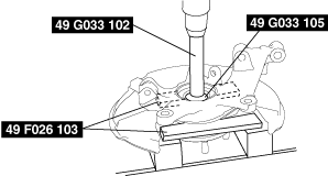
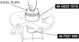
Dust Cover Installation Note
1. Mark the new dust cover in the same way as the removed one.
ac9uuw00001766
|
2. Align the marks of the new dust cover and the knuckle.
3. Install the new dust cover using the SSTs.
ac9wzw00000813
|
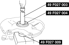
Wheel Bearing Installation Note
1. Install the new wheel bearing using the SSTs.
ac9uuw00001768
|
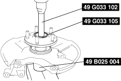
Wheel Hub Installation Note
1. Install the wheel hub using the SSTs.
ac9uuw00001769
|
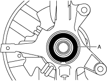
Wheel Hub, Steering Knuckle Component Installation Note
1. Apply grease (D4Y0 33247) to the wheel bearing inner race and drive shaft contact surface (Area A in figure).
acxuuw00003013
|
2. Install the wheel hub, steering knuckle component.
Locknut (Crimped-fix Type) Installation Note
1. Install a new locknut and stake it as shown.
ac9wzw00000814
|