|
1
|
VERIFY FREEZE FRAME DATA HAS BEEN RECORDED
• Has the FREEZE FRAME DATA been recorded on the repair order?
|
Yes
|
Go to the next step.
|
|
No
|
Record the FREEZE FRAME DATA on the repair order, then go to the next step.
|
|
2
|
VERIFY RELATED REPAIR INFORMATION AVAILABILITY
• Verify related Service Information availability.
• Is any related repair information available?
|
Yes
|
Perform repair or diagnosis according to the available repair information.
• If the vehicle is not repaired, go to the next step.
|
|
No
|
Go to the next step.
|
|
3
|
VERIFY DTC HAVE BEEN PRESENTED
• Switch the ignition OFF (LOCK), then switch it ON (Engine off).
• Read the DTC in the BCM.
• Is the DTC B1318 output?
|
Yes
|
Perform the “DTC B1318 Troubleshooting”.
|
|
No
|
Go to the next step.
|
|
4
|
INSPECT TCM CONNECTOR FOR POOR CONNECTION
• Switch the ignition OFF (LOCK).
• Disconnect the TCM connector.
• Inspect for poor connection (such as damaged/pulled-out pins, corrosion).
• Is there any malfunction?
|
Yes
|
Repair or replace the terminal, then go to Step 15.
|
|
No
|
Go to the next step.
|
|
5
|
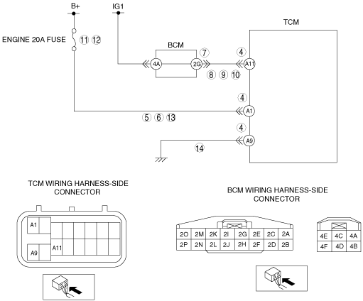
INSPECT B+ CIRCUIT
• Disconnect the TCM connector.
• Switch the ignition ON (Engine off).
• Measure the voltage between the TCM terminal A1 (wiring harness-side) and body GND.
• Is the voltage B+?
|
Yes
|
Go to go to Step 9.
|
|
No
|
Go to the next step.
|
|
6
|
INSPECT B+ CIRCUIT FOR SHORT TO GND
• Switch the ignition OFF (LOCK).
• Disconnect both battery cables.
• Inspect for continuity between TCM terminal A1 (wiring harness-side) and body GND.
• Is there continuity?
|
Yes
|
Repair or replace the wiring harness for a possible short to GND, then go to Step 15.
|
|
No
|
Go to the next step.
|
|
7
|
INSPECT BCM CONNECTOR FOR POOR CONNECTION
• Switch the ignition OFF (LOCK).
• Disconnect the BCM connector.
• Inspect for poor connection (such as damaged/pulled-out pins, corrosion).
• Is there any malfunction?
|
Yes
|
Repair or replace the terminal, then go to Step 15.
|
|
No
|
Go to the next step.
|
|
8
|
INSPECT IG1 CIRCUIT FOR OPEN CIRCUIT
• Switch the ignition OFF (LOCK).
• Inspect for continuity between BCM terminal 2G (wiring harness-side) and TCM terminal A11 (wiring harness-side).
• Is there continuity?
|
Yes
|
Go to the next step.
|
|
No
|
Repair or replace the wiring harness for a possible open circuit, then go to Step 15.
|
|
9
|
INSPECT IG1 CIRCUIT
• Disconnect the TCM connector.
• Switch the ignition ON (Engine off).
• Measure the voltage between the TCM terminal A11 (wiring harness-side) and body GND.
• Is the voltage B+?
|
Yes
|
Go to go to Step 14.
|
|
No
|
Go to the next step.
|
|
10
|
INSPECT IG1 CIRCUIT FOR SHORT TO GND
• Switch the ignition OFF (LOCK).
• Disconnect both battery cables.
• Inspect for continuity between TCM terminal A11 (wiring harness-side) and body GND.
• Is there continuity?
|
Yes
|
Repair or replace the wiring harness for a possible short to GND, then go to Step 15.
|
|
No
|
Go to the next step.
|
|
11
|
INSPECT ENGINE 20A FUSE
• Switch the ignition OFF (LOCK).
• Inspect the ENGINE 20A fuse for proper installation and failure.
• Is it normal?
|
Yes
|
Go to the next step.
|
|
No
|
• If the fuse is not installed correctly, install it correctly, then go to Step 15.
• If fuse has been melted, replace it, then go to Step 15.
|
|
12
|
INSPECT ENGINE 20A FUSE TERMINAL FOR POOR CONNECTION
• Switch the ignition OFF (LOCK).
• Inspect for poor connection (such as damaged, corrosion)
• Is there any malfunction?
|
Yes
|
Repair or replace the terminal, then go to Step 15.
|
|
No
|
Go to the next step.
|
|
13
|
INSPECT B+ CIRCUIT FOR OPEN CIRCUIT
• Switch the ignition OFF (LOCK).
• Inspect for continuity between battery positive terminal (wiring harness-side) and TCM terminal A1 (wiring harness-side).
• Is there continuity?
|
Yes
|
Go to the next step.
|
|
No
|
Repair or replace the wiring harness for a possible open circuit, then go to Step 15.
|
|
14
|
INSPECT GND CIRCUIT FOR OPEN CIRCUIT
• Switch the ignition OFF (LOCK).
• Inspect for continuity between TCM terminal A9 (wiring harness-side) and body GND.
• Is there continuity?
|
Yes
|
Go to the next step.
|
|
No
|
Repair or replace the wiring harness for a possible open circuit, then go to the next step.
|
|
15
|
VERIFY DTC TROUBLESHOOTING COMPLETED
• Make sure to reconnect all the disconnected connectors.
• Clear the DTC using the M-MDS.
• Perform the following procedure to ensure that the DTC has been resolved:
-
1. Start the engine.
2. Warm up the engine and transaxle.
3. Drive the vehicle in D position and make sure that the gears shift smoothly from 1GR to 6GR.
• Is the same DTC present?
|
Yes
|
Replace the TCM, then go to the next step.
|
|
No
|
Go to the next step.
|
|
16
|
VERIFY NO DTCs ARE PRESENT
• Perform the “Reading DTCs Procedure”.
• Are any DTCs present?
|
Yes
|
Go to the applicable DTC inspection.
|
|
No
|
DTC troubleshooting completed.
|