 |
ac9uuw00001965
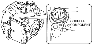
TCM INSPECTION [AW6A-EL, AW6AX-EL]
id051723800300
Control Module Inspection
1. Remove the air cleaner component. (See INTAKE-AIR SYSTEM REMOVAL/INSTALLATION [MZI-3.7].)
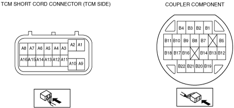
2. Measure the voltage at each TCM connector (wiring harness-side) terminal and refer to the terminal voltage table.
Terminal Voltage Table (Reference)
ac9uuw00001965
|
|
Terminal |
Signal |
Connected to |
Test condition |
Voltage (V) |
Inspection item (s) |
|
|---|---|---|---|---|---|---|
|
A1
|
Battery back up supply
|
Battery
|
Constant
|
B+
|
• Inspect battery
• Inspect related harness
|
|
|
A3
|
Up switch
(Selector lever component)
|
Up switch
(Selector lever component)
|
Shift up
(M range)
|
Below 1.0
|
• Inspect selector lever component
• Inspect related harness
|
|
|
Other ranges, all positions
|
B+
|
|||||
|
A4
|
Down switch
(Selector lever component)
|
Down switch
(Selector lever component)
|
Shift down
(M range)
|
Below 1.0
|
• Inspect selector lever component
• Inspect related harness
|
|
|
Other ranges, all positions
|
B+
|
|||||
|
A5
|
Starter lock output signal
|
PCM
|
Shift the selector lever to P or N position.
|
Ignition switch ON
|
B+
|
• Inspect PCM
• Inspect related harness
|
|
Ignition switch OFF
|
Below 1.0
|
|||||
|
A6
|
CAN_L
|
PCM
|
Because this terminal is for serial communication, good/no good judgment by terminal voltage is not possible. Carry out inspection according to DTCs.
|
—
|
• Inspect related harness
|
|
|
A7
|
M range switch
|
M range switch
|
M range
|
Below 1.0
|
• Inspect selector lever component
• Inspect related harness
|
|
|
Other positions, all ranges
|
B+
|
|||||
|
A11
|
Power supply
|
Ignition switch
|
Ignition switch ON
|
B+
|
• Inspect Ignition switch
• Inspect related harness
|
|
|
Ignition switch OFF
|
Below 1.0
|
|||||
|
A13
|
Back-up light relay
|
Back-up light relay
|
Ignition switch ON
|
Shift the selector lever to R position.
|
Below 1.0
|
• Inspect back-up light relay
(See RELAY INSPECTION)
• Inspect related harness
|
|
Other
|
B+
|
|||||
|
A14
|
CAN_H
|
PCM
|
Because this terminal is for serial communication, good/no good judgment by terminal voltage is not possible. Carry out inspection according to DTCs.
|
—
|
• Inspect related harness
|
|
3. Remove the TCM. (See TCM REMOVAL/INSTALLATION [AW6A-EL, AW6AX-EL].)
4. Verify that continuity or resistance at terminal is as indicated in the terminal continuity/resistance table.
ac9uuw00002728
|
Terminal Continuity/Resistance Table (Reference)
ac9uuw00002703
|
|
Terminal |
Signal |
Connected to |
Test Condition |
Continuity/Resistance |
Inspection item (s) |
|
|---|---|---|---|---|---|---|
|
A9
|
System GND
|
GND
|
Constant
|
Continuity
|
• Inspect related harness
|
|
|
B1
|
Line pressure control solenoid control GND
|
Line pressure control solenoid
|
• Inspect resistance between couple component terminals B3 and B1 (wiring harness-side).
|
ATF temperature: 20°C {68°F}
|
5.0—5.6 (ohms)
|
• Inspect line pressure control solenoid
• Inspect related harness
|
|
B2
|
Shift solenoid B control
|
Shift solenoid B
|
ATF temperature: 20°C {68°F}
|
11—15 (ohms)
|
• Inspect shift solenoid B
• Inspect related harness
|
|
|
B3
|
Line pressure control solenoid control
|
Line pressure control solenoid
|
• Inspect resistance between couple component terminals B3 and B1 (wiring harness-side).
|
ATF temperature: 20°C {68°F}
|
5.0—5.6 (ohms)
|
• Inspect line pressure control solenoid
• Inspect related harness
|
|
B4
|
TCC control solenoid control GND
|
TCC control solenoid
|
• Inspect resistance between couple component terminals B9 and B4 (wiring harness-side).
|
ATF temperature: 20°C {68°F}
|
5.0—5.6 (ohms)
|
• Inspect TCC control solenoid
• Inspect related harness
|
|
B5
|
Shift solenoid A control
|
Shift solenoid A
|
ATF temperature: 20°C {68°F}
|
11—15 (ohms)
|
• Inspect shift solenoid A
• Inspect related harness
|
|
|
B7
|
TFT sensor GND
|
TFT sensor
|
• Inspect resistance between couple component terminals B7 and B8 (wiring harness-side).
|
ATF temperature: 10°C {50°F}
|
5.62—7.31 (kilohms)
|
• Inspect TFT sensor
• Inspect related harness
|
|
ATF temperature: 25°C {77°F}
|
Approx. 3.5 (kilohms)
|
|||||
|
B8
|
TFT sensor
|
ATF temperature: 110°C {230°F}
|
0.22—0.27 (kilohms)
|
|||
|
B9
|
TCC control solenoid control
|
TCC control solenoid
|
• Inspect resistance between couple component terminals B9 and B4 (wiring harness-side).
|
ATF temperature: 20°C {68°F}
|
5.0—5.6 (ohms)
|
• Inspect TCC control solenoid
• Inspect related harness
|
|
B10
|
Shift solenoid C control GND
|
Shift solenoid C
|
• Inspect resistance between couple component terminals B11 and B10 (wiring harness-side).
|
ATF temperature: 20°C {68°F}
|
5.0—5.6 (ohms)
|
• Inspect shift solenoid C
• Inspect related harness
|
|
B11
|
Shift solenoid C control
|
|||||
|
B12
|
Input/turbine speed sensor (–)
|
Input/turbine speed sensor
|
• Inspect for continuity between couple component terminals B12 and B13 (wiring harness-side).
|
Continuity
|
• Inspect input/turbine speed sensor
• Inspect related harness
|
|
|
B13
|
Input/turbine speed sensor (+)
|
|||||
|
B14
|
Shift solenoid E control
|
Shift solenoid E
|
• Inspect resistance between couple component terminals B14and B22 (wiring harness-side).
|
ATF temperature: 20°C {68°F}
|
5.0—5.6 (ohms)
|
• Inspect shift solenoid E
• Inspect related harness
|
|
B16
|
Shift solenoid F control GND
|
Shift solenoid F
|
• Inspect resistance between couple component terminals B21and B16 (wiring harness-side).
|
ATF temperature: 20°C {68°F}
|
5.0—5.6 (ohms)
|
• Inspect shift solenoid F
• Inspect related harness
|
|
B17
|
Shift solenoid D control
|
Shift solenoid D
|
• Inspect resistance between couple component terminals B17and B18 (wiring harness-side).
|
ATF temperature: 20°C {68°F}
|
5.0—5.6 (ohms)
|
• Inspect shift solenoid D
• Inspect related harness
|
|
B18
|
Shift solenoid D control GND
|
|||||
|
B19
|
Vehicle speed (–)
|
VSS
|
• Inspect for continuity between couple component terminals B19 and B20 (wiring harness-side).
|
Continuity
|
• Inspect VSS
• Inspect related harness
|
|
|
B20
|
Vehicle speed (+)
|
VSS
|
||||
|
B21
|
Shift solenoid F control
|
Shift solenoid F
|
• Inspect resistance between couple component terminals B21and B16 (wiring harness-side).
|
ATF temperature: 20°C {68°F}
|
5.0—5.6 (ohms)
|
• Inspect shift solenoid F
• Inspect related harness
|
|
B22
|
Shift solenoid E control GND
|
Shift solenoid E
|
• Inspect resistance between couple component terminals B14and B22 (wiring harness-side).
|
ATF temperature: 20°C {68°F}
|
5.0—5.6 (ohms)
|
• Inspect shift solenoid E
• Inspect related harness
|
5. Perform the neutral position learning. (See NEUTRAL POSITION LEARNING [AW6A-EL, AW6AX-EL])