 |
am6xuw00004151
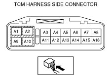
TCM INSPECTION [AY6A-EL, AY6AX-EL]
id0517k3330900
1. Remove the fresh-air duct and air cleaner component as a single unit. (See INTAKE-AIR SYSTEM REMOVAL/INSTALLATION [MZI-3.7].)
2. Connect the voltmeter (-) lead to body GND.
3. Measure the voltage at each terminal.
Terminal Voltage Table (Reference)
am6xuw00004151
|
|
Terminal |
Connected to |
Test condition |
Voltage (V) |
Inspection item (s) |
|---|---|---|---|---|
|
A1
|
Battery
|
Under any condition
|
B+
|
• Battery
(See BATTERY INSPECTION [MZI-3.7].)
• Related harness
|
|
A2
|
—
|
—
|
—
|
—
|
|
A3
|
Up switch
|
Selector lever up-shift position
|
Below 1.0
|
• Up switch
• Related harness
|
|
Except selector lever up-shift position
|
B+
|
|||
|
A4
|
Down switch
|
Selector lever down-shift position
|
Below 1.0
|
• Down switch
• Related harness
|
|
Except selector lever down-shift position
|
B+
|
|||
|
A5
|
PCM
|
Ignition switch ON
|
B+
|
• PCM
(See PCM INSPECTION [MZI-3.7].)
• Related harness
|
|
Ignition switch off
|
Below 1.0
|
|||
|
A6
|
CAN_L
|
Because this terminal is for CAN, no valid determination of terminal voltage is possible.
|
||
|
A7
|
M position switch
|
M position
|
Below 1.0
|
• M position switch
• Related harness
|
|
Except M position
|
B+
|
|||
|
A8
|
—
|
—
|
—
|
—
|
|
A9
|
GND
|
Under any condition
|
Continuity
|
• Related harness
|
|
A10
|
—
|
—
|
—
|
—
|
|
A11
|
Ignition switch
|
Ignition switch ON
|
B+
|
• Related harness
|
|
Ignition switch off
|
Below 1.0
|
|||
|
A12
|
—
|
—
|
—
|
—
|
|
A13
|
Back-up light relay
|
Selector lever R position
|
B+
|
• Back-up light relay
(See RELAY INSPECTION.)
• Related harness
|
|
Except selector lever R position
|
Below 1.0
|
|||
|
A14
|
CAN_H
|
Because this terminal is for CAN, no valid determination of terminal voltage is possible.
|
||
|
A15
|
—
|
—
|
—
|
—
|
|
A16
|
—
|
—
|
—
|
—
|