STEP
INSPECTION
ACTION
1
• Start the engine, and drive the vehicle.
-
― Does the speedometer needle move smoothly?― Does the speedometer needle indicate correct speed?
Yes
Troubleshooting completed.
No
Go to the next step.
2
• Inspect the DTC for the instrument cluster ON-BOARD DIAGNOSTIC SYSTEM.
• Has DTC U2023 been recorded in memory?
Yes
Go to the next step.
No
Go to Step 4.
3
• Inspect the FREEZE FRAME DATA for DTC U2023.
• Has the speedometer fail-safe function been requested?
Yes
Inspect the DTC for the PCM, DSC/RSC HU/CM and TCM.
(See ON-BOARD DIAGNOSIS [DSC/RSC].)
No
Go to the next step.
4
• Start the instrument cluster input/output check mode.
• Inspect the speedometer using the check code 12.
• Is the speedometer normal?
Yes
Inspect the PCM, TCM, or connectors.
No
Replace the instrument cluster.
5
• Disconnect the negative battery cable.
• Measure the resistance between the DLC-2 terminals F and E.
• Is the resistance below 60 ohms?
Yes
Go to the next step.
No
Go to Step 7.
6
• Disconnect the negative battery cable.
• Inspect the DLC-2 terminals F and E for short to power supply or ground.
• Is there any malfunction?
Yes
Inspect the wiring harness and CAN system-related module.
Repair or replace the malfunctioning part.
No
Replace the instrument cluster.
7
• Turn the ignition switch to the LOCK position.
• Inspect the instrument cluster connector terminals for poor connection (such as damaged/pulled-out pins, and corrosion).
• Are the terminals normal?
Yes
Go to the next step.
No
Repair or replace the terminal.
8
• Disconnect the negative battery cable.
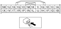
• Measure the resistance between the instrument cluster connector terminals 1W and 1X.
• Is the resistance 114—126 ohms?
Yes
Inspect the wiring harness and CAN system-related module.
Repair or replace the malfunctioning part.
No
Replace the instrument cluster.