 |
ac9uuw00000862
ON-BOARD DIAGNOSIS [DSC/RSC]
id0402b3810100
On-Board Diagnostic (OBD) Test Description
Read/clear diagnostic results
PID/Data monitor and record
Active command modes
Reading DTCs Procedure
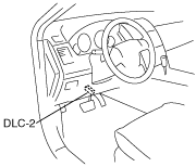
1. Connect the M-MDS to the DLC-2.
ac9uuw00000862
|
2. After the vehicle is identified, select the following items from the initialization screen of the M-MDS.
3. Verify the DTC according to the directions on the screen.
4. After completion of repairs, clear all DTCs stored in the DSC/RSC. (See Clearing DTCs Procedures.)
Clearing DTCs Procedures
1. Connect the M-MDS to the DLC-2.
ac9uuw00000862
|
2. After the vehicle is identified, select the following items from the initialization screen of the M-MDS.
3. Verify the DTC according to the directions on the screen.
4. Press the clear button on the DTC screen to clear the DTC.
5. Turn the ignition switch to the LOCK position.
6. Turn the ignition switch to the ON position and wait for 5 s or more.
7. Perform DTC inspection. (See Reading DTCs Procedure.)
8. Verify that no DTCs are displayed.
PID/Data Monitor and Record Procedure
1. Connect the M-MDS to the DLC-2.
ac9uuw00000862
|
2. After the vehicle is identified, select the following items from the initialization screen of the M-MDS.
3. Select the applicable PID from the PID table.
4. Verify the PID data according to the directions on the screen.
Active Command Modes Procedure
1. Connect the M-MDS to the DLC-2.
ac9uuw00000862
|
2. After the vehicle is identified, select the following items from the initialization screen of the M-MDS.
3. Select the active command modes from the PID table.
4. Perform the active command modes, inspect the operations for each parts.
DTC Table
|
DTC |
System malfunction location |
Page |
|---|---|---|
|
M-MDS |
||
|
B1317
|
Power supply system
|
(See DTC B1317, B1318 [DSC/RSC].)
|
|
B1318
|
Power supply system
|
(See DTC B1317, B1318 [DSC/RSC].)
|
|
B1342
|
DSC/RSC HU/CM system
|
(See DTC B1342, C1730 [DSC/RSC].)
|
|
C1095
|
Pump motor, motor relay system
|
(See DTC C1095, C1096 [DSC/RSC].)
|
|
C1096
|
Pump motor, motor relay system
|
(See DTC C1095, C1096 [DSC/RSC].)
|
|
C1115
|
Valve relay system
|
|
|
C1145
|
RF ABS wheel-speed sensor (open circuit) system
|
|
|
C1155
|
LF ABS wheel-speed sensor (open circuit) system
|
|
|
C1165
|
RR ABS wheel-speed sensor (open circuit) system
|
|
|
C1175
|
LR ABS wheel-speed sensor (open circuit) system
|
|
|
C1185
|
Valve relay system
|
|
|
C1194
|
LF outlet solenoid valve system
|
|
|
C1198
|
LF inlet solenoid valve system
|
|
|
C1210
|
RF outlet solenoid valve system
|
|
|
C1214
|
RF inlet solenoid valve system
|
|
|
C1222
|
ABS wheel-speed sensor system
|
(See DTC C1222 [DSC/RSC].)
|
|
C1233
|
LF ABS wheel-speed sensor/ABS sensor rotor system
|
|
|
C1234
|
RF ABS wheel-speed sensor/ABS sensor rotor system
|
|
|
C1235
|
RR ABS wheel-speed sensor/ABS sensor rotor system
|
|
|
C1236
|
LR ABS wheel-speed sensor/ABS sensor rotor system
|
|
|
C1242
|
LR outlet solenoid valve system
|
|
|
C1246
|
RR outlet solenoid valve system
|
|
|
C1250
|
LR inlet solenoid valve system
|
|
|
C1254
|
RR inlet solenoid valve system
|
|
|
C1278
|
Steering angle sensor system
|
|
|
C1280
|
SAS control module system
|
|
|
C1282
|
SAS control module system
|
|
|
C1288
|
Brake fluid pressure sensor system
|
(See DTC C1288 [DSC/RSC]
|
|
C1295
|
Steering angle sensor system
|
|
|
C1327
|
Brake fluid level sensor system
|
(See DTC C1327 [DSC/RSC].)
|
|
C1329
|
RF outlet solenoid valve coil system
|
|
|
C1330
|
LR outlet solenoid valve coil system
|
|
|
C1331
|
RR outlet solenoid valve coil system
|
|
|
C1332
|
LF outlet solenoid valve coil system
|
|
|
C1333
|
LR inlet solenoid valve coil system
|
|
|
C1334
|
LF inlet solenoid valve coil system
|
|
|
C1335
|
RF inlet solenoid valve coil system
|
|
|
C1336
|
RR inlet solenoid valve coil system
|
|
|
C1404
|
RH traction control solenoid valve system
|
|
|
C1410
|
LH traction control solenoid valve system
|
|
|
C1446
|
Brake switch system
|
(See DTC C1446 [DSC/RSC].)
|
|
C1516
|
SAS control module system
|
|
|
C1527
|
RH traction control solenoid valve coil system
|
|
|
C1528
|
LH traction control solenoid valve coil system
|
|
|
C1530
|
RH stability control solenoid valve coil system
|
|
|
C1531
|
LH stability control solenoid valve coil system
|
|
|
C1730
|
DSC/RSC HU/CM system
|
(See DTC B1342, C1730 [DSC/RSC].)
|
|
C1950
|
SAS control module system
|
|
|
C1957
|
RH stability control solenoid valve system
|
|
|
C1958
|
LH stability control solenoid valve system
|
|
|
C1963
|
SAS control module (Yaw rate sensor part) initial point correction error
|
(See DTC C1963 [DSC/RSC].)
|
|
C1991
|
DSC/RSC sensor (abnormal initialization) system
|
(See DTC C1991 [DSC/RSC].)
|
|
C2770
|
SAS control module system
|
|
|
U0073
|
CAN system communication error
|
|
|
U0100
|
Communication error to PCM
|
|
|
U0140
|
Communication error to BCM
|
|
|
U0155
|
Communication error to instrument cluster
|
|
|
U1901
|
SAS control module system (CAN2 line malfunction)
|
(See DTC U1901 [DSC/RSC].)
|
|
U2023
|
Steering angle sensor system
|
PID/DATA Monitor Table
|
PID name (definition) |
Unit/Condition |
Operation condition (reference) |
Action |
|---|---|---|---|
|
ACCLMTR
|
G
|
• Vehicle stopped or driving at constant speed: 0 G
• Vehicle is driving at a acceleration: changes 0 G—positive
• Vehicle is driving at a deceleration: changes 0 G—negative
|
Perform the DTC inspection for the SAS control module.
(See DTC DISPLAY.)
(See DTC TABLE.)
|
|
BOO_ABS
(Brake pedal switch input)
|
Off/On
|
• Brake pedal released: Off
• Brake pedal depressed: On
|
Inspect the brake switch.
(See BRAKE SWITCH INSPECTION.)
|
|
CCNTABS
(Number of continuous codes)
|
—
|
Indicates number of DTC
|
Perform the DTC inspection.
(See DTC Table.)
|
|
LAT_ACCL
|
G
|
• Vehicle stopped or driving at constant speed: 0 G
• Cornering to right: Changes 0 G—positive
• Cornering to left: Changes 0 G—negative
|
Perform the DTC inspection for the SAS control module.
(See DTC DISPLAY.)
(See DTC TABLE.)
|
|
MCYLI P
|
MPa, psi
|
• Brake pedal depressed: Changes according to the brake fluid pressure
|
Inspect the brake fluid pressure sensor.
|
|
PMP_MOTOR
(Pump motor output state)
|
Off/On
|
• Pump motor not activated: Off
• Pump motor activated: On
|
Inspect the DSC/RSC HU/CM.
(See DSC/RSC SYSTEM INSPECTION.)
|
|
PWR_RLY
(Valve relay output state)
|
Off/On
|
• Valve relay not activated: Off
• Valve relay activated: On
|
Inspect the DSC/RSC HU/CM.
(See DSC/RSC SYSTEM INSPECTION.)
|
|
ROLL_RATE
(Roll rate sensor input)
|
°/s
|
• Vehicle stopped or driving straight: 0 °/s
• Cornering to left: 0 °/s—positive
• Cornering to right: 0 °/s—negative
|
Perform the DTC inspection for the SAS control module.
(See DTC DISPLAY.)
(See DTC TABLE.)
|
|
SHIFT_P
(Transaxle gear position input)
|
Off/On
|
• Other than those above: Off
• Selector lever position P: On
|
Inspect the TCM.
|
|
SWA_POS
(Steering angle sensor input)
|
°
|
• Steering wheel neutral position(not turned): 0 °
• Steering wheel turned to left: Changes 0 °—negative
• Steering wheel turned to right: Changes 0 °—positive
|
Inspect the steering angle sensor.
|
|
TCS_OFF_SW
(TCS OFF switch input)
|
Off/On
|
• TCS OFF switch is released: Off
• TCS OFF switch is depressed: On
|
Inspect the TCS OFF switch.
(See TCS OFF SWITCH INSPECTION.)
|
|
V_LF_INL
(Left front inlet solenoid valve output state)
|
Off/On
|
• Solenoid valve not activated: Off
• Solenoid valve activated: On
|
Inspect the DSC/RSC HU/CM.
(See DSC/RSC SYSTEM INSPECTION.)
|
|
V_LF_OTL
(Left front outlet solenoid valve output state)
|
Off/On
|
• Solenoid valve not activated: Off
• Solenoid valve activated: On
|
Inspect the DSC/RSC HU/CM.
(See DSC/RSC SYSTEM INSPECTION.)
|
|
V_LR_INL
(Left rear inlet solenoid valve output state)
|
Off/On
|
• Solenoid valve not activated: Off
• Solenoid valve activated: On
|
Inspect the DSC/RSC HU/CM.
(See DSC/RSC SYSTEM INSPECTION.)
|
|
V_LR_OTL
(Left rear outlet solenoid valve output state)
|
Off/On
|
• Solenoid valve not activated: Off
• Solenoid valve activated: On
|
Inspect the DSC/RSC HU/CM.
(See DSC/RSC SYSTEM INSPECTION.)
|
|
V_RF_INL
(Right front inlet solenoid valve output state)
|
Off/On
|
• Solenoid valve not activated: Off
• Solenoid valve activated: On
|
Inspect the DSC/RSC HU/CM.
(See DSC/RSC SYSTEM INSPECTION.)
|
|
V_RF_OTL
(Right front outlet solenoid valve output state)
|
Off/On
|
• Solenoid valve not activated: Off
• Solenoid valve activated: On
|
Inspect the DSC/RSC HU/CM.
(See DSC/RSC SYSTEM INSPECTION.)
|
|
V_RR_INL
(Right rear inlet solenoid valve output state)
|
Off/On
|
• Solenoid valve not activated: Off
• Solenoid valve activated: On
|
Inspect the DSC/RSC HU/CM.
(See DSC/RSC SYSTEM INSPECTION.)
|
|
V_RR_OTL
(Right rear outlet solenoid valve output state)
|
Off/On
|
• Solenoid valve not activated: Off
• Solenoid valve activated: On
|
Inspect the DSC/RSC HU/CM.
(See DSC/RSC SYSTEM INSPECTION.)
|
|
V_STB_L
(LH stability control solenoid valve output state)
|
Off/On
|
• Solenoid valve not activated: Off
• Solenoid valve activated: On
|
Inspect the DSC/RSC HU/CM.
(See DSC/RSC SYSTEM INSPECTION.)
|
|
V_STB_R
(RH stability control solenoid valve output state)
|
Off/On
|
• Solenoid valve not activated: Off
• Solenoid valve activated: On
|
Inspect the DSC/RSC HU/CM.
(See DSC/RSC SYSTEM INSPECTION.)
|
|
V_TRC_L
(LH traction control solenoid valve output state)
|
Off/On
|
• Solenoid valve not activated: Off
• Solenoid valve activated: On
|
Inspect the DSC/RSC HU/CM.
(See DSC/RSC SYSTEM INSPECTION.)
|
|
V_TRC_R
(RH traction control solenoid valve output state)
|
Off/On
|
• Solenoid valve not activated: Off
• Solenoid valve activated: On
|
Inspect the DSC/RSC HU/CM.
(See DSC/RSC SYSTEM INSPECTION.)
|
|
WSPD_LF
(Left front ABS wheel-speed sensor input)
|
KPH, MPH
|
• Vehicle stopped: 0 KPH, 0 MPH
• Vehicle running: vehicle speed
|
Inspect the front ABS wheel-speed sensor.
|
|
WSPD_LR
(Left rear ABS wheel-speed sensor input)
|
KPH, MPH
|
• Vehicle stopped: 0 KPH, 0 MPH
• Vehicle running: vehicle speed
|
Inspect the rear ABS wheel-speed sensor.
|
|
WSPD_RF
(Right front ABS wheel-speed sensor input)
|
KPH, MPH
|
• Vehicle stopped: 0 KPH, 0 MPH
• Vehicle running: vehicle speed
|
Inspect the front ABS wheel-speed sensor.
|
|
WSPD_RR
(Right rear ABS wheel-speed sensor input)
|
KPH, MPH
|
• Vehicle stopped: 0 KPH, 0 MPH
• Vehicle running: vehicle speed
|
Inspect the rear ABS wheel-speed sensor.
|
|
YAW_RATE
|
°/s
|
• Vehicle stopped or driving straight: 0 °/s
• Cornering to left: Changes 0 °/s—negative
• Cornering to right: Changes 0 °/s—positive
|
Perform the DTC inspection for the SAS control module.
(See DTC DISPLAY.)
(See DTC TABLE.)
|
Active Command Modes Table
|
Command name |
Output part |
Operation |
Operating condition |
|---|---|---|---|
|
PMP_MOTOR
|
Pump motor
|
Off/On
|
Ignition switch at ON
|
|
PWR_RLY
|
Valve relay
|
||
|
SSR_INTL
|
DSC/RSC sensor initialization
|
||
|
V_LF_INL
|
LF inlet solenoid valve
|
||
|
V_LF_OTL
|
LF outlet solenoid valve
|
||
|
V_LR_INL
|
LR inlet solenoid valve
|
||
|
V_LR_OTL
|
LR outlet solenoid valve
|
||
|
V_RF_INL
|
RF inlet solenoid valve
|
||
|
V_RF_OTL
|
RF outlet solenoid valve
|
||
|
V_RR_INL
|
RR inlet solenoid valve
|
||
|
V_RR_OTL
|
RR outlet solenoid valve
|
||
|
V_STB_L
|
LH stability control solenoid valve
|
||
|
V_STB_R
|
RH stability control solenoid valve
|
||
|
V_TRC_L
|
LH traction control solenoid valve
|
||
|
V_TRC_R
|
RH traction control solenoid valve
|