ENGINE CONTROL SYSTEM OPERATION INSPECTION [MZI-3.7]
id0103d2803700
Input Signal System Inspection Procedure
1. Find an irregular signal. (See Finding irregular signals.)
2. Locate source. (See Locating the source of unusual signals.)
3. Repair or replace the malfunctioning part.
4. Confirm that the irregular signal is no longer detected.
Finding irregular signals
While referring to, use the PID/DATA monitor and record function to inspect the input signal system relating to the problem.
1. Start the engine and idle the vehicle. You can assume that any signals that are out of specification by a wide margin are irregular.
2. When recreating the problem, any sudden change in monitor input signals that is not intentionally created by the driver can be determined as irregular.
Locating the source of unusual signals
-
Caution
-
• Compare the M-MDS monitor voltage with the measurement voltage using the digital measurement system function. If you use another tester, misreading may occur.
• When measuring voltage, attach the tester GND to the GND of the PCM that is being tested, or to the engine itself. If this is not performed, the measured voltage and actual voltage may differ.
• After connecting the pin to a waterproof coupler, confirming continuity and measuring the voltage, inspect the waterproof connector for cracks. If there are any, use sealant to fix them. Failure to do this may result in deterioration of the wiring harness or terminal from water damage, leading to problems with the vehicle.
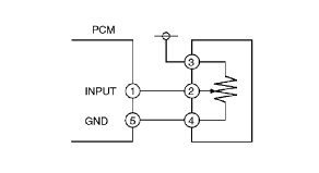
Variable resistance type 1 (TP sensor)
Input signal system inspection for variable resistance type 1
1. When an irregular signal is detected, measure the #1 PCM terminal voltage.
-
• If the #1 terminal voltage and the M-MDS monitor voltage are the same, proceed to the next step.
• If there is a difference of 0.5 V or more, inspect for the following points concerning the PCM connector:
-
― Female terminal opening is loose.
― Coupler (pin holder) damage
― Pin discoloration (blackness)
― Harness/pin crimp is loose or disconnected.
2. Measure the #2 sensor terminal voltage.
-
• If there is a 0.5 V or more difference between the sensor and the M-MDS voltages, inspect the wiring harness for open or short circuits.
• If the sensor and the M-MDS voltages are the same, inspect for the following points concerning the sensor connector:
-
― Female terminal opening is loose.
― Coupler (pin holder) damage
― Pin discoloration (blackness)
• If there are no problems, proceed to next investigation below.
Standard power supply system inspection for variable resistance type 1
-
• Confirm that the #3 terminal is at 5 V.
-
― If the measured voltage on the #3 terminal is 5 V, inspect the following points on the sensor connector.
― If there is no problem, inspect for the following:
-
• Female terminal opening is loose.
• Coupler (pin holder) damage
• Pin discoloration (blackness)
― If the #3 terminal measures other than 5 V, inspect for the following:
-
• Open or short circuit in wiring harness
• Harness/pin crimp is loose or disconnected.
GND system inspection for variable resistance type 1
-
• Confirm that terminal sensor #5 is at 0 V.
-
― If it is at 0 V, inspect the sensor.
-
• If necessary, replace the sensor.
― If not, inspect for the following:
-
• Open or short circuit in wiring harness
• Female terminal opening is loose causing an open or short circuit in wiring harness
• Coupler (pin holder) damage
• Pin discoloration (blackness)
• Harness/pin crimp is loose or disconnected.
Variable resistance type 2 (mass air flow (MAF) sensor and VSS)
GND system inspection for variable resistance type 2
-
• Confirm that terminal sensor #4 is at 0 V.
-
― If it is at 0 V, inspect the sensor.
-
• If necessary, replace the sensor.
― If not at 0 V, inspect for the following:
-
• Open circuit in wiring harness
• Female terminal opening is loose.
• Coupler (pin holder) damage
• Pin discoloration (blackness)
• Harness/pin crimp is loose or disconnected.
Input signal system inspection for variable resistance type 2
1. When an irregular signal is detected, measure the #1 PCM terminal voltage.
-
• If the #1 terminal voltage and the M-MDS monitor voltage are the same, proceed to the next step.
• If there is a difference of 0.5 V or more, inspect for the following points concerning the PCM connector:
-
― Female terminal opening is loose.
― Coupler (pin holder) damage
― Pin discoloration (blackness)
― Harness/pin crimp is loose or disconnected.
2. Measure the #2 sensor terminal voltage.
-
• If there is a 0.5 V or more difference between the sensor and the M-MDS voltages, inspect the wiring harness for open or short circuits.
• If the sensor and the M-MDS voltages are the same, inspect the following points concerning the sensor connector:
-
― Female terminal opening is loose.
― Coupler (pin holder) damage
― Pin discoloration (blackness)
― Harness/pin crimp is loose or disconnected.
• If there are no problems, proceed to next investigation below.
Electrical supply system inspection for variable resistance type 2
-
• Confirm that the sensor #3 terminal is B+.
-
― If the measured voltage on the #3 terminal is B+, inspect the following points on the sensor connector.
― If there is no problem, inspect for the following:
-
• Female terminal opening is loose.
• Coupler (pin holder) damage
• Pin discoloration (blackness)
― If the #3 terminal measures other than B+, inspect the following:
-
• Open or short circuit in wiring harness
• Harness/pin crimp is loose or disconnected.
Thermistor type (IAT sensor and CHT sensor)
Input signal system inspection for thermistor type
1. When an irregular signal is detected, measure the #1 PCM terminal voltage.
-
• If the #1 terminal voltage and the M-MDS monitor voltage are the same, proceed to the next step.
• If there is a difference of 0.5 V or more, inspect the following points concerning the PCM connector:
-
― Female terminal opening loose
― Coupler (pin holder) damage
― Pin discoloration (blackness)
― Harness/pin crimp is loose or disconnected.
2. Measure the #2 sensor terminal voltage.
-
• If there is a 0.5 V or more difference between the sensor and the M-MDS voltages, inspect the wiring harness for open or short circuits.
• If the sensor and the M-MDS voltages are the same, inspect the following points concerning the sensor connector:
-
― Female terminal opening is loose.
― Coupler (pin holder) damage
― Pin discoloration (blackness)
― Harness/pin crimp is loose or disconnected.
• If there are no problems, proceed to next investigation below.
GND system inspection for thermistor type
-
• Confirm that terminal sensor #3 is at 0 V.
-
― If it is at 0 V, inspect the sensor. If necessary, replace the sensor.
― If not, inspect for the following:
-
• Open circuit in wiring harness
• Female terminal opening is loose.
• Coupler (pin holder) damage
• Pin discoloration (blackness)
• Harness/pin crimp is loose or disconnected.
Main Relay Operation Inspection
1. Verify that the main relay clicks when the ignition switch is turned to ON position and off.
-
• If there is no operation sound, inspect the following:
-
― Harness and connector between battery and main relay terminal A.
― Harness and connector between PCM terminal 1Q and main relay terminal E.
Electronic Throttle Control System Inspection
Engine coolant temperature compensation inspection
1. Connect the M-MDS to the DLC-2.
2. Access the following PIDs:
-
• ECT
• IAT
• RPM
3. Verify that the engine is cold, then start the engine.
4. Verify that the engine speed decreases as the engine warms up.
-
• If the engine speed does not decrease or decreases slowly, inspect the following:
-
― CHT sensor and related wiring harness
― Electronic throttle body and related wiring harness
Load compensation inspection
1. Start the engine and idle it.
2. Connect the M-MDS to the DLC-2.
3. Verify that P0506, P0507 is not displayed.
-
• If P0506, P0507 are displayed, perform DTC inspection.
4. Access the RPM PID.
-
Note
-
• Excludes temporary idle speed drop just after the loads are turned on.
5. Verify that the engine speed is within the specification under each load condition.
-
• If load condition is not as specified, inspect the following:
-
― A/C switch and related wiring harness
― Fan switch and related wiring harness
Throttle position (TP) sweep inspection
1. Connect the M-MDS to the DLC-2.
2. Turn the ignition switch to the ON position.
3. Verify that none of the following DTC are displayed:
-
• P0122, P0123, P0222, P0223, P2101, P2107, P2112, P2122, P2123, P2127, P2128, P2135
-
― If any one DTC is displayed, perform DTC inspection.
4. Access TP1, TP2 PID.
5. Verify that the PID reading is within the CTP value. (See PCM INSPECTION [MZI-3.7].)
-
• If the PID reading is out of range, perform the following:
-
― Remove the air duct from the throttle valve body.
― Verify that the throttle valve opens when the accelerator pedal is depressed.
-
• If the throttle valve opens, inspect the throttle position sensor and related wiring harness.
• If the throttle valve does not open, inspect the throttle actuator control motor and related wiring harness.
6. Gradually depress the throttle pedal and verify that the PID reading increases accordingly.
-
• If the PID reading drops momentarily, inspect the following:
-
― Throttle position sensor
7. Fully depress the throttle pedal and verify that the PID reading is within WOT value. (See PCM INSPECTION [MZI-3.7].)
-
• If the PID reading is out of range, perform the followings:
-
― Remove the air duct from throttle valve body.
― Verify that the throttle valve opens when throttle pedal is depressed.
-
• If the throttle valve opens, inspect the throttle position sensor and related wiring harness.
• If the throttle valve does not open, inspect the throttle actuator control motor and related wiring harness.
Fuel Injector Operation Inspection
|
STEP
|
INSPECTION
|
RESULTS
|
ACTION
|
|
1
|
While cranking the engine, inspect for fuel injector operation sound at each cylinder using a soundscope.
Is operation sound heard?
|
Yes
|
Fuel injector operation is normal.
|
|
No
|
All cylinders not heard:
Go to the next step.
Some cylinders not heard:
Go to Step 3.
|
|
2
|
Perform main relay operation inspection.
Is main relay operation normal?
|
Yes
|
Inspect the following:
• Fuel injector power system related wiring harness and connectors
• PCM connectors
• Fuel injector GND and related wiring harness and connectors
|
|
No
|
Repair or replace malfunctioning parts.
|
|
3
|
Switch fuel injector connector of not operating fuel injector with operating fuel injector.
Is operation sound heard?
|
Yes
|
Go to the next step.
|
|
No
|
Replace the fuel injector.
|
|
4
|
Are wiring harness and connectors of not operation fuel injector normal? (Open or short)
|
Yes
|
Inspect PCM terminal voltage of fuel injector signal.
|
|
No
|
Repair or replace malfunctioning parts.
|
Fuel Cut Control System Inspection
-
Note
-
• This inspection has to perform after the Fuel Injector Operation Inspection.
If simulation function of the M-MDS is used:
1. Warm up the engine and idle it.
2. Connect the M-MDS to the DLC-2.
3. Select the RPM and FUELSYS1 PIDs.
4. Monitor the both PIDs while performing the following steps.
- (1) Depress the accelerator pedal and increase the RPM PID to 4,000 rpm.
- (2) Quickly release the accelerator pedal (brake pedal is not depressed) and verify that the FUELSYS1 PID is OL, and CL. when the RPM PID drops below 1,200 rpm.
-
-
• If not as specified, inspect the following.
-
― CHT sensor and related harness
― TR switch and related wiring harness
If simulation function of the M-MDS is not used:
1. Warm up the engine and idle it.
2. Measure the fuel injector control signal wave profile using the oscilloscope while performing the following steps.
- (1) Depress the accelerator pedal and increase the engine speed to 4,000 rpm.
- (2) Quickly release the accelerator pedal (brake pedal is not depressed) and verify that the wave profile constant B+, and appears wave, when the engine speed drops below 2,200 rpm.
-
-
• If not as specified, inspect the following.
-
― CHT sensor and related harness
― TR switch and related wiring harness
Fuel Pump Operation Inspection
1. Remove the fuel-filler cap.
2. Turn the ignition switch to the ON position.
3. Turn the fuel pump relay from off to on using the FP PID and inspect if the operation sound is heard.
-
• If no operation sounds is heard, proceed to next step.
4. Measure voltage at wiring harness side fuel pump connector terminal B.
-
Specification
-
B+ (Ignition switch at on)
-
• If the voltage is as specified, inspect the following:
-
― Fuel pump continuity
― Fuel pump GND
― Wiring harness between fuel pump relay and PCM terminal 1V
• If not as specified, inspect the following:
-
― Fuel pump relay
― Wiring harness connector (Main relay—fuel pump relay—fuel pump)
Fuel Pump Control System Inspection
1. Crank the engine and verify that fuel pump relay operation sound is heard.
2. If operation sound is not heard, inspect the following:
-
• Wiring harness and connectors (Main relay—fuel pump relay—PCM terminal 1V)
Spark Test
1. Disconnect the fuel pump relay.
2. Verify that each ignition coil and connector is connected properly.
3. Inspect the ignition system in the following procedure.
-
Warning
-
• High voltage in the ignition system can cause strong electrical shock which can result in serious injury. Avoid direct contact to the vehicle body during the following spark test.
|
STEP
|
INSPECTION
|
ACTION
|
|
1
|
• Disconnect the ignition coil from the spark plugs.
• Remove the spark plugs.
-
― Ensure that the spark plugs don't have carbon deposits.
• Are the spark plugs OK?
|
Yes
|
Go to the next step.
|
|
No
|
Perform 2 times of no-load racing at 4000rpm for 2 min to burn off the carbon deposits.
Then repeat this step.
|
|
2
|
• Inspect the spark plugs for damage, wear, and proper plug gap.
• Are the spark plugs normal?
|
Yes
|
Go to the next step.
|
|
No
|
Replace spark plugs, then go to the next step.
|
|
3
|
• Reconnect the spark plugs to the ignition coil.
• Ground the spark plugs to the engine.
• Is a strong blue spark visible at each cylinder while cranking?
|
Yes
|
Ignition system is normal.
|
|
No
|
Some cylinders do not spark:
• Go to the next step.
All cylinders do not spark:
• Go to Step 5.
|
|
4
|
• Inspect the following wiring harnesses for open or short:
-
― Ignition coil No.1 terminal C—PCM terminal 2A
― Ignition coil No.2 terminal C—PCM terminal 2F
― Ignition coil No.3 terminal C—PCM terminal 2K
― Ignition coil No.4 terminal C—PCM terminal 2W
― Ignition coil No.5 terminal C—PCM terminal 2AA
― Ignition coil No.6 terminal C—PCM terminal 2AE
• Are the wiring harnesses normal?
|
Yes
|
Inspect and replace the ignition coil.
|
|
No
|
Repair or replace the malfunctioning part, then go to Step 1.
|
|
5
|
• Measure the voltage at terminal A in each ignition coils.
• Is the voltage B+?
|
Yes
|
Go to the next step.
|
|
No
|
Inspect power supply circuit of ignition coils.
|
|
6
|
Verify continuity between each ignition coils terminal B and battery negative post.
Is there any continuity?
|
Yes
|
Go to the next step.
|
|
No
|
Inspect GND circuit of ignition coils.
|
|
7
|
• Does the PCM connector or ignition coil connectors have poor connection?
|
Yes
|
Repair or replace the connector, then go to Step 1.
|
|
No
|
Go to the next step.
|
|
8
|
• Are the following parts normal?
-
― CKP sensor and crankshaft pulley
|
Yes
|
Inspect for open or short circuit in wiring harness and connector of CKP sensor.
|
|
No
|
Repair or replace the malfunctioning part, then go to Step 1.
|
Purge Control System Inspection
If simulation function of the M-MDS is used:
1. Start the engine.
2. Disconnect the vacuum hose between the purge solenoid valve and the charcoal canister.
3. Put the finger to the purge solenoid valve and verify that there is no vacuum applied when the engine is cold.
-
• If there is a vacuum, inspect the following:
-
― Wiring harness and connectors (Purge solenoid valve—PCM terminal 1BC)
― Purge solenoid vale (stuck open)
4. Connect the M-MDS to the DLC-2 and verify that the DTC P0443 is shown. Perform the DTC inspection.
(See DTC TABLE [MZI-3.7].)
5. Select EVAPCP PID.
6. Increase the duty value of the purge valve to 50 % and inspect if the operation sound of the valve is heard.
-
• If the operation sound is heard, inspect for the loose or damaged vacuum hose. (Intake manifold—purge solenoid valve—charcoal canister)
• If the operation sound is not heard, perform the purge solenoid valve inspection.
7. Warm up the engine to normal operating temperature.
8. Monitor the EVAPCP PID using the M-MDS, and drive the vehicle approx. 2,000 rpm for 30 sec. or more.
-
• If the EVAPCP PID is 0 %, inspect the following.
-
― MAF, APP1, APP2, APP3, TP REL and LOAD PIDs.
If simulation function of the M-MDS is not used:
1. Start the engine.
2. Disconnect the vacuum hose between the purge solenoid valve and the charcoal canister.
3. Put the finger to the purge solenoid valve and verify that there is no vacuum applied when the engine is cold.
-
• If there is a vacuum, inspect the following:
-
― Wiring harness and connectors (Purge solenoid valve—PCM terminal 1BC)
― Purge solenoid vale (stuck open)
4. Connect the M-MDS to the DLC-2 and verify that the DTC P0443 is shown. Perform the DTC inspection.
(See DTC TABLE [MZI-3.7].)
5. Access EVAPCP and ECT PIDs.
6. Verify that the ECT PID is more than 78 °C {173 °F}.
-
• If the ECT PID reading indicates less than 78 °C {173 °F}, perform the ECT inspection.
7. Set the vehicle on the dynamometer or chassis roller.
-
Warning
-
• When the dynamometer or chassis roller is operating, there is a possibility that the operator may come into contact with or be caught up in the rotating parts, leading to serious injuries or death. When performing work while the dynamometer or chassis roller is operating, be careful not to come into contact with or caught up in any of the rotating parts.
8. Drive the vehicle approx. 2,000 rpm for 30 sec. or more.
-
• If there is no vacuum, inspect the following:
-
― Wiring harness and connector (Main relay—purge solenoid valve—PCM terminal 1BC)
― Purge solenoid valve
― MAF, APP1, APP2, APP3, TP REL and LOAD PIDs
-
• If there is vacuum, inspect the following:
-
― Vacuum hose (Purge solenoid valve—charcoal canister)
A/C Cut-off Control System Inspection
1. Start the engine.
2. Turn the A/C switch and the fan switch on.
3. Verify that the A/C compressor magnetic clutch actuates.
-
• If it does not actuate, go to symptom troubleshooting “No.23 A/C does not work sufficiently“.
4. Fully open the throttle valve and verify that the A/C compressor magnetic clutch does not actuate for 2—5 s.
-
• If it actuates, inspect as follows:
-
― A/C relay
― Open or short to GND circuit in wiring harness and connectors (Ignition switch—A/C relay—PCM terminal 1N)
― A/C related parts
― APP1, APP2, APP3 PIDs
Cooling Fan Control System Inspection
1. Connect the M-MDS to the DLC-2.
2. Start the engine and warm it up to normal operating temperature.
3. Perform the KOER self-test. (See KOEO/KOER SELF TEST [MZI-3.7].)
4. Verify that the DTC P0480 is not shown and the cooling fan operates during the KOER self-test.
-
• If DTC P0480 is shown, perform the DTC troubleshooting procedure.
• If the cooling fans do not operate, proceed to the following:
-
1. Verify the clicking sound of the cooling fan relay when the ignition switch is turned from the off to the ON position.
2. If there is no the clicking sound, inspect the cooling fan relay for an open circuit between the ignition switch and the cooling fan relay.
• If there is a clicking sound, go to the next step.
• Inspect the following parts in the indicated order in accordance with fan operation conditions.
Cooling fans do not operate
-
• Inspect and repair for followings;
-
― Open circuit between the fan control module and the cooling fan relay
― Open circuit between fan control module and ground
― Poor connection of the fan control module connector
• If there is no malfunction, replace the fan control module.
Cooling fan motor No.1 does not operate
-
• Inspect and repair for followings;
-
― Open or short to ground circuit between the fan control module and cooling fan motor No.1
― Poor connection of the fan control module connector or cooling fan motor No.1 connector
• If there is no malfunction, replace the fan control module.
Cooling fan motor No.2 does not operate
-
• Inspect and repair for followings;
-
― Open or short to ground circuit between the fan control module and the cooling fan motor No.2
― Poor connection of the fan control module connector or the cooling fan motor No.1 connector
• If there is no malfunction, replace the fan control module.
Variable Valve Timing Control System Operation Inspection
When idling cannot be continued
-
Note
-
1. Remove the OCV and verify that the spool valve is at maximum retard position.
-
2. Connect the OCV.
3. Turn the ignition switch to ON position.
4. Verify that the spool valve is at max. retard position.
-
• If the spool valve is stuck in advance direction, inspect the following:
-
― Short circuit in harnesses or connectors between the OCV and the PCM.
5. Inspect the variable valve timing actuator.
When idling can be continued
For right bank
1. Disconnect OCV (RH) connector.
2. Warm up the engine and it at idle.
3. Apply the battery voltage to the OCV and verify that the engine idles roughly or stalls.
-
• If the engine idles roughly or stalls, inspect the timing chain component (valve timing deviation).
• If the engine does not idle roughly or stall, go to the next step.
4. Remove the OCV (RH) and perform spool valve operation inspection. (See OIL CONTROL VALVE (OCV) REMOVAL/INSTALLATION [MZI-3.7].)
-
• If not as specified, inspect the following:
-
― OCV (RH)
― Harnesses and connectors between OCV (RH) and PCM have an open or short circuit.
• If as specified, inspect the following right bank hydraulic passages for clogging or leakage, or both.
-
― Oil pressure switch - OCV
― OCV - camshaft
― Camshaft internal passage
5. If they are normal, replace the right bank camshaft pulley (with built-in variable valve timing actuator).
When idling can be continued
For left bank
1. Disconnect OCV (LH) connector.
2. Warm up the engine to idle.
3. Apply the battery voltage to the OCV and verify that the engine idles roughly or stalls.
-
• If the engine idles roughly or stalls, inspect the timing chain component (valve timing deviation).
• If the engine does not idle roughly or stall, go to the next step.
4. Remove the OCV (LH) and perform spool valve operation inspection. (See OIL CONTROL VALVE (OCV) REMOVAL/INSTALLATION [MZI-3.7].)
-
• If not as specified, inspect the following:
-
― OCV (LH)
― Harnesses and connectors between OCV (LH) and PCM have an open or short circuit.
• If as specified, inspect the following left bank hydraulic passages for clogging or leakage or both.
-
― Oil pressure switch - OCV
― OCV - camshaft
― Camshaft internal passage
5. If they are normal, replace the left bank camshaft pulley (with built-in variable valve timing actuator).
Evaporative Emission (EVAP) System Leak Inspection
• To verify that the problem has been fixed properly after repairs, the run drive cycle or EVAP system leak inspection must be performed.
EVAP system leak inspection using the M-MDS
-
Note
-
• Use the IDS (laptop PC) because the PDS (Pocket PC) does not support the EVAP system test.
-
EVAP system test out line
-
• The EVAP system test, which can substituted for the run drive cycle as an EVAP control system repair confirmation method, can detect the small / large leak or blockage without run-drive cycle.
-
Note
-
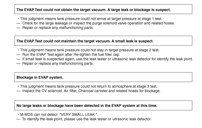
• The M-MDS can not detect “VERY SMALL LEAK”.To identify the leak point, please use the leak tester or ultrasonic leak detector.
-
EVAP system test description
-
• The EVAP system test finds gas leaks or blockage of EVAP system using the changes of the fuel tank pressure.
-
― This test starts after sending an on-demand test signal from the M-MDS to the PCM.
― This test consists of three stages, and each stage is performed automatically as follows:
Stage 1 test. (Test for large leak or blockage)
-
• The M-MDS send the stage 1 test start signal to the PCM.
• PCM controls the CV solenoid valve and purge solenoid valve to control the tank pressure to the targeted value.
• The M-MDS detect the large leak or the purge line blockage if the tank pressure does not arrive at the target vacuum in specified period.
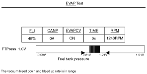
Stage 2 test. (Test for small leak)
-
• When fuel tank pressure arrived at the targeted pressure at stage 1 test, the M-MDS send the stage 2 test signal to the PCM to turn off the purge solenoid to keep the tank pressure.
• The M-MDS detect the small leak if the tank pressure can not keep within the target in specified period.
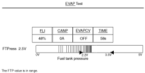
Stage 3 test. (Test for blockage)
-
• The M-MDS send the stage 3 test signal to the PCM to turn off the CV solenoid for check the blockage of EVAP system.
• The M-MDS detect blockage of the CV solenoid valve or air filter if the tank pressure does not arrive at the target (atmosphere).
-
EVAP system malfunction judgment
-
• The M-MDS detect the small / large leak or blockage based on fuel tank pressure at the end of EVAP Test.
-
Evaporative system test procedure
-
1. Verify that all PIDs within the following specifications.
-
Note
-
• To successfully perform this procedure, all PIDs must be within the specifications before proceeding to the next step.
2. Select the following items from the initialization screen of the M-MDS.
-
1. Select the “Powertrain“.
2. Select the “Fuel“.
3. Select the “EVAP Test“.
-
• Verify that ECT and IAT are within the specifications at the confirmation screen.To successfully perform this procedure, ECT and IAT must be within the spec before proceeding to the next step.
• Fuel Level must be maintained within 15%—85%. PCM will cancel the EVAP Test If the Fuel Level is lower than 15% or higher than 85%.
3. Verify the test results described on the M-MDS and follow the instructions.