TRANSFER OIL SEAL (COMPANION FLANGE) REPLACEMENT


id031600803600

1.  Remove the front pipe. (See EXHAUST SYSTEM REMOVAL/INSTALLATION [MZI-3.7].)

2.  Remove the transverse member. (See TRANSVERSE MEMBER REMOVAL/INSTALLATION.)

3.  Remove the propeller shaft. (See PROPELLER SHAFT REMOVAL/INSTALLATION.)

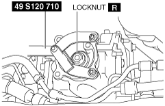
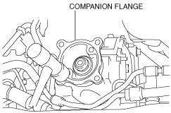
4.  Remove the oil seal.

Note
•  Always measure the initial torque of the companion flange and record the measurement before removing the oil seal. If the measurement of the initial torque and the recording are not performed, the companion flange cannot be installed correctly and the transfer will have to be replaced with a new one.
(1)  Measure the initial torque of the companion flange using a torque wrench.
ac9wzw00003177
(2)  Record the measured initial torque (this initial torque is “initial torque A”).
(3)  Lock the companion flange against rotation using the SST (49 S120 710) and remove the locknut.
ac9wzw00003178
(4)  Remove the companion flange using the SST (49 0839 425C).
ac9wzw00003179
(5)  Insert the two tapping screws into the groove of the oil seal.
ac9wzw00003180
(6)  Pry the screws using a fastener remover to remove the oil seal.
ac9wzw00003197

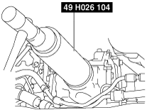
5.  Install the new oil seal.

(1)  Install the new oil seal using the SST (49 H026 104) and a hammer.
ac9wzw00003181
(2)  Install the companion flange using a hammer.
ac9wzw00003182
(3)  Lock the companion flange against rotation using the SST (49 S120 710).
ac9wzw00003183
(4)  Tighten the new locknut so that there are no gaps on the contacting surface between the companion flange and the transfer case.
Caution
•  Gradually tighten the locknut while verifying the initial torque of the companion flange (this initial torque is "initial torque B”).
•  Tighten the locknut so that initial torque B is within the range of ±0.3 N·m {3.1 kgf·cm, 27 in·lbf} relative to initial torque A.
•  If the locknut is tightened with excessive force and initial torque B is not within the range of ±0.3 N·m {3.1 kgf·cm, 27 in·lbf} relative to initial torque A, the transfer will have to be replaced with a new one because the spacer in the transfer will have been damaged.
(5)  Tighten the locknut using a torque wrench while verifying the initial torque of the companion flange (this initial torque is "initial torque B").
ac9wzw00003177
(6)  Verify that initial torque B is within the range of ±0.3 N·m {3.1 kgf·cm, 27 in·lbf} relative to initial torque A.
•  If initial torque B is not within the range of ±0.3 N·m {3.1 kgf·cm, 27 in·lbf} relative to initial torque A, replace the transfer with a new one. (See TRANSFER REMOVAL/INSTALLATION.)

6.  Install the propeller shaft. (See PROPELLER SHAFT REMOVAL/INSTALLATION.)

7.  Install the transverse member. (See TRANSVERSE MEMBER REMOVAL/INSTALLATION.)

8.  Install the front pipe. (See EXHAUST SYSTEM REMOVAL/INSTALLATION [MZI-3.7].)