 |
ac9uuw00001688
TRANSFER REMOVAL/INSTALLATION
id031600800600
1. Disconnect the negative battery cable.
2. Remove the front tire. (RH) (See GENERAL PROCEDURES (SUSPENSION).)
3. Disconnect the rear HO2S (RH) connector. (See REAR HEATED OXYGEN SENSOR (HO2S) REMOVAL/INSTALLATION [MZI-3.7].)
4. Remove the following parts:
5. Disconnect the propeller shaft from the transfer side. (See PROPELLER SHAFT REMOVAL/INSTALLATION.)
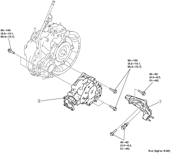
6. Remove in the order indicated in the table.
7. Install in the reverse order of removal.
8. Warm up the engine and transaxle, inspect for oil leakage, and inspect the transfer operation.
ac9uuw00001688
|
|
1
|
Transfer bracket
|
|
2
|
Transfer
(See Transfer Removal Note.)
(See Transfer Installation Note.)
|
Transfer Removal Note
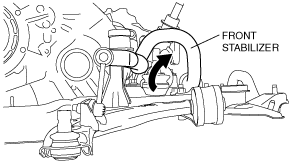
1. Disconnect the front stabilizer control link, and rotate the stabilizer to the front to secure a space from the side.
ac9uuw00001689
|
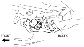
2. Remove the No.1 engine mount bolt C.
ac9uuw00003036
|
3. Remove the transfer installation bolts.
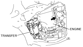
4. Push the engine forward so that the front side of the transfer faces downward, then remove the transfer.
ac9uuw00001691
|
Transfer Installation Note
1. Push the engine forward so that the front side of the transfer faces downward, then install the transfer.
ac9uuw00001692
|
2. Install the transfer installation bolts.
3. Tighten the No.1 engine mount bolt C at the specified torque.
ac9uuw00003036
|
4. Rotate the front stabilizer to the rear to set it in its original position.
ac9uuw00001693
|
Transfer Bracket Installation Note
1. Install the transfer bracket to the transfer, then temporarily tighten bolt C.
ac9uuw00002213
|
2. Temporarily tighten bolt A and B.
3. Tighten bolt A, B and C in the order of C→A→B.
4. Tighten bolt D.