 |
ac9wzw00000239
POWER BRAKE UNIT REMOVAL/INSTALLATION [R.H.D.]
id041100801852
1. Remove the windshield wiper arm and blade. (See WINDSHIELD WIPER ARM AND BLADE REMOVAL/INSTALLATION.)
2. Remove the cowl grill. (See COWL GRILLE REMOVAL/INSTALLATION.)
3. Remove the windshield wiper motor. (See WINDSHIELD WIPER MOTOR REMOVAL/INSTALLATION.)
4. Remove the cowl panel. (See COWL PANEL REMOVAL/INSTALLATION.)
5. Remove the master cylinder component. (See MASTER CYLINDER REMOVAL/INSTALLATION [R.H.D.].)
6. Disconnect the rear HO2S (RH) connector. (See REAR HEATED OXYGEN SENSOR (HO2S) REMOVAL/INSTALLATION [MZI-3.7].)
7. Remove the exhaust manifold insulator (RH). (See EXHAUST SYSTEM REMOVAL/INSTALLATION [MZI-3.7].)
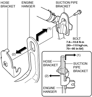
8. Remove the bolt shown in the figure, and move the suction pipe bracket in the direction of arrow (1) to disconnect it from the engine hanger.
ac9wzw00000239
|
9. Move the hose bracket in the direction of arrow (2) to disconnect it from the engine hanger.
ac9wzw00000237
|
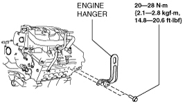
10. Remove the engine hanger (RH).
ac9wzw00000600
|
11. Set the rear HO2S (RH) connector bracket out of the way.
12. Disconnect the oil control valve (OCV) connector. (See OIL CONTROL VALVE (OCV) REMOVAL/INSTALLATION [MZI-3.7].)
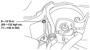
13. Remove the nuts as shown in the figure, and set the front cooler pipe and hose out of the way.
ac9wzw00000159
|
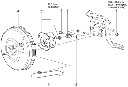
14. Remove in the order indicated in the table.
15. Remove the brake switch. (See BRAKE PEDAL REMOVAL/INSTALLATION [R.H.D.].)
16. Install in the reverse order of removal.
17. After installation, add brake fluid, bleed the air, and inspect for fluid leakage. (See AIR BLEEDING.)
18. Inspect the brake pedal. (See BRAKE PEDAL INSPECTION [R.H.D.].)
ac9wzw00000160
|
|
1
|
Vacuum hose
|
|
2
|
Snap pin
|
|
3
|
Clevis pin
|
|
4
|
Fork
|
|
5
|
Nut
|
|
6
|
Power brake unit
|
|
7
|
Gasket, spacer
|