DTC P0717 [AW6AX-EL]
id0502j6801500
DTC P0717 |
Input/turbine speed sensor circuit malfunction (open circuit/short circuit) |
---|---|
DETECTION CONDITION
|
• When all conditions below are satisfied.
• Normal turbine speed signal is not input.
Diagnostic support note:
• This is a continuous monitor (CCM).
• The MIL illuminates if the TCM detects the above malfunction condition during the first drive cycle.
• A PENDING CODE is not available.
• FREEZE FRAME DATA is available.
• The AT warning light illuminates.
• The DTC is stored in the TCM memory.
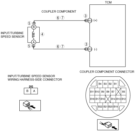
|
POSSIBLE CAUSE
|
• Input/turbine speed sensor malfunction
• Open circuit between input/turbine speed sensor terminal B and TCM terminal B12
• Open circuit between input/turbine speed sensor terminal A and TCM terminal B13
• Short to ground in wiring harness between input/turbine speed sensor terminal B and TCM terminal B12
• Short to ground in wiring harness between input/turbine speed sensor terminal A and TCM terminal B13
• Short to power in wiring harness between input/turbine speed sensor terminal B and TCM terminal B12
• Short to power in wiring harness between input/turbine speed sensor terminal A and TCM terminal B13
• Damaged connector between input/turbine speed sensor and TCM
• TCM malfunction
|
![]() |
Diagnostic procedure
STEP |
INSPECTION |
ACTION |
|
---|---|---|---|
1
|
VERIFY FREEZE FRAME DATA HAS BEEN RECORDED
• Has the FREEZE FRAME DATA been recorded?
|
Yes
|
Go to the next step.
|
No
|
Record the FREEZE FRAME DATA on the repair order, then go to the next step.
|
||
2
|
VERIFY RELATED REPAIR INFORMATION AVAILABILITY
• Verify related Service Information availability.
• Is any related repair information available?
|
Yes
|
Perform repair or diagnosis according to the available repair information.
• If the vehicle is not repaired, go to the next step.
|
No
|
Go to the next step.
|
||
3
|
INSPECT TERMINAL COUPLE COMPONENT FOR POOR CONNECTION
• Turn the ignition switch to the LOCK position.
• Remove the TCM.
• Inspect for poor connection (such as damaged/pulled-out pins, corrosion).
• Are terminals normal?
|
Yes
|
Go to the next step.
|
No
|
Replace the couple component, then go to Step 8.
|
||
4
|
INSPECT CONTINUITY OF INPUT/TURBINE SPEED SENSOR CIRCUIT
• Inspect for continuity between the couple component terminals B12 and B13 (wiring harness-side).
• Is there continuity?
|
Yes
|
Go to go to Step 8.
|
No
|
Go to the next step.
|
||
5
|
INSPECT TERMINAL INPUT/TURBINE SPEED SENSOR FOR POOR CONNECTION
• Disconnect the input/turbine speed sensor connector.
• Inspect for poor connection (such as damaged/pulled-out pins, corrosion).
• Are terminals normal?
|
Yes
|
Go to the next step.
|
No
|
Replace the couple component, then go to Step 8.
|
||
6
|
INSPECT TERMINAL COUPLE COMPONENT CIRCUIT FOR OPEN CIRCUIT
• Inspect for continuity between couple component terminals (wiring harness-side) and input/turbine speed sensor terminals (wiring wiring harness-side).
• Is there continuity?
|
Yes
|
Go to the next step.
|
No
|
Repair or replace the couple component, then go to Step 8.
|
||
7
|
INSPECT TERMINAL COUPLE COMPONENT CIRCUIT FOR SHORT TO CIRCUIT
• Inspect for continuity between couple component terminals (wiring harness-side).
• Is there continuity?
|
Yes
|
Repair or replace the couple component, then go to the next step.
|
No
|
Replace the input/turbine speed sensor, then go to the next step.
|
||
8
|
VERIFY TROUBLESHOOTING OF DTC P0717 COMPLETED
• Make sure to reconnect all the disconnected connectors.
• Clear the DTC from the memory using the M-MDS.
• Drive the vehicle in D range and make sure that gears shift smoothly from 1GR to 6GR.
• Is the same DTC present?
|
Yes
|
Replace the TCM, then go to the next step.
|
No
|
Go to the next step.
|
||
9
|
VERIFY AFTER REPAIR PROCEDURE
• Perform the “After Repair Procedure”.
• Are any DTCs present?
|
Yes
|
Go to the applicable DTC inspection.
(See DTC TABLE [AW6AX-EL].)
|
No
|
DTC troubleshooting completed.
|