 |
ac9uuw00002735
SOLENOID VALVE INSPECTION [AW6AX-EL]
id0517j6801900
Resistance Inspection (On-Vehicle Inspection)
1. Disconnect the negative battery cable.
2. Remove the air cleaner component. (See INTAKE-AIR SYSTEM REMOVAL/INSTALLATION [MZI-3.7].)
3. Remove the TCM. (See TCM REMOVAL/INSTALLATION [AW6AX-EL].)
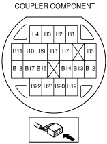
4. Measure the resistance between the following terminals.
ac9uuw00002735
|
ac9uuw00002727
|
Solenoid valve resistance (ATF temperature: 20 °C {68 °F})
|
Terminal |
Solenoid valve |
Resistance (ohm) |
|---|---|---|
|
B5—GND
|
Shift solenoid A
|
11—15
|
|
B2—GND
|
Shift solenoid B
|
11—15
|
|
B11—B10
|
Shift solenoid C
|
5.0—5.6
|
|
B17—B18
|
Shift solenoid D
|
5.0—5.6
|
|
B14—B22
|
Shift solenoid E
|
5.0—5.6
|
|
B21—B16
|
Shift solenoid F
|
5.0—5.6
|
|
B9—B4
|
TCC control solenoid
|
5.0—5.6
|
|
B3—B1
|
Line pressure control solenoid
|
5.0—5.6
|
5. Install the TCM. (See TCM REMOVAL/INSTALLATION [AW6AX-EL].)
6. Install the air cleaner component. (See INTAKE-AIR SYSTEM REMOVAL/INSTALLATION [MZI-3.7].)
7. Connect the negative battery cable.
Continuity Inspection (On-Vehicle Inspection)
1. Disconnect the negative battery cable.
2. Remove the air cleaner component. (See INTAKE-AIR SYSTEM REMOVAL/INSTALLATION [MZI-3.7].)
3. Remove the TCM. (See TCM REMOVAL/INSTALLATION [AW6AX-EL].)
4. Verify that there is no continuity between coupler component terminals B1, B3, B4, B9, B10, B11, B14, B17, B18, B21, B22 and GND.
5. Install the TCM. (See TCM REMOVAL/INSTALLATION [AW6AX-EL].)
6. Install the air cleaner component. (See INTAKE-AIR SYSTEM REMOVAL/INSTALLATION [MZI-3.7].)
7. Connect the negative battery cable.