|
ac9uuw00001588
SELECTOR LEVER COMPONENT REMOVAL/INSTALLATION
id051800800800
1. Disconnect the negative battery cable.
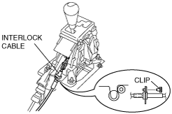
2. To remove the interlock cable, remove the following parts.
3. To remove the selector cable, remove the following parts.
4. To remove the selector lever, remove the following parts.
5. Remove in the order shown in the figure.
6. Install in the reverse order of removal.
L.H.D.
ac9uuw00001588
|
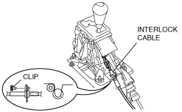
R.H.D.
ac9wzw00000035
|
|
1
|
Clip
|
|
2
|
Clip
|
|
3
|
Clip
|
|
4
|
Lock unit connector
|
|
5
|
Interlock cable
|
|
6
|
Clip
|
|
7
|
Clip
|
|
8
|
Selector cable
|
|
9
|
Selector lever component connector
|
|
10
|
Selector lever component
|
|
11
|
Selector lever knob
|
|
12
|
Selector lever panel
|
|
13
|
Selector lever
|
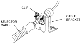
Selector Cable Removal Note
1. Remove the clip.
2. Remove the selector cable.
ac9uuw00001591
|
3. Remove the selector cable from the cable bracket.
ac9uuw00001592
|
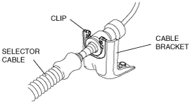
Selector Cable Installation Note
1. Install the selector cable and clip to the bracket as shown in the figure.
ac9uuw00001593
|
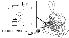
2. Verify that the selector lever is in the P position.
3. Lock the lock piece of the selector cable (selector lever side) in the order shown in the figure.
L.H.D.
ac9wzw00000019
|
R.H.D.
ac9wzw00000020
|
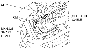
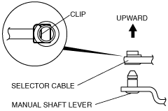
4. Verify that the manual shaft is in the P position.
ac9uuw00001595
|
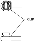
5. Install the clip as shown in the figure.
ac9uuw00001596
|
ac9uuw00001597
|
6. Install the selector lever to the manual shaft lever so that no load acts on the selector cable.
7. Confirm that the tip of the manual shaft lever projects out of the end of the selector cable.
8. Securely install the selector cable to the selector cable bracket.
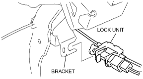
Interlock Cable Installation Note
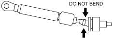
1. Push the interlock cable.
ac9uuw00001598
|
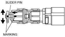
2. Verify that the marking on the slider pin is positioned as shown in the figure.
L.H.D.
ac9uuw00001599
|
R.H.D.
ac9wzw00000029
|
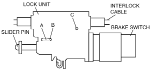
3. Push the a 1.5mm {0.059 in} round bar or similar into hole A by fully pushing the slider pin in.
ac9uuw00001600
|
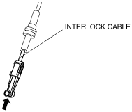
4. Fully pull the end of the interlock cable.
ac9uuw00001601
|
5. Push the a 1.5mm {0.059 in} round bar or similar into hole B and hole C of the lock unit until it passes through.
ac9uuw00001600
|
6. Disconnect the brake switch connector.
7. Remove the brake switch. (See BRAKE PEDAL REMOVAL/INSTALLATION [L.H.D.].)(See BRAKE PEDAL REMOVAL/INSTALLATION [R.H.D.].)
8. Install a new brake switch. (See BRAKE PEDAL REMOVAL/INSTALLATION [L.H.D.].)(See BRAKE PEDAL REMOVAL/INSTALLATION [R.H.D.].)
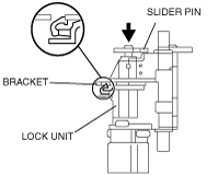
9. With the slider pin pressed, slide the lock unit to fix the lock unit hook into the bracket hole securely as shown in the figure.
ac9uuw00001602
|
10. Rotate the slider pin to release the lock and verify that it slides freely.
11. Pull the slider pin outward until it contacts the brake pedal stopper rubber and rotate the slider pin to lock.
ac9wzw00000030
|
12. Verify that the selector lever in the P position.
13. Install the interlock cable end to the cam pin on the selector lever.
L.H.D.
ac9wzw00000605
|
R.H.D
ac9wzw00000606
|
14. Fit the interlock cable in the U–groove in the selector lever base plate and install the clip.
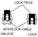
15. Press the interlock cable lock piece in until it is locked.
ac9uuw00001604
|
16. Remove the a 1.5mm {0.059 in} round bar or similar from the lock unit holes A, B, and C.
ac9uuw00001600
|
17. Connect the brake switch connector with the brake pedal released.
18. Turn the ignition switch to ON position.
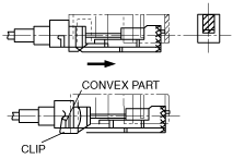
19. Install the interlock cable to the steering lock.
20. Slide the outer casing to the steering lock and insert the clip over the convex part of the outer casing.
ac9uuw00001605
|