 |
ac9wzw00002218
VARIABLE VALVE TIMING ACTUATOR REMOVAL/INSTALLATION [MZI-3.7]
id0110c5801100
1. Drain the engine oil. (See ENGINE OIL REPLACEMENT [MZI-3.7].)
2. Remove the engine and transaxle component. (See ENGINE REMOVAL/INSTALLATION [MZI-3.7].)
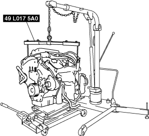
3. Secure the engine and transaxle component using a hoist and the SST.
ac9wzw00002218
|
4. Remove the dynamic chamber and throttle body as a single unit. (See INTAKE-AIR SYSTEM REMOVAL/INSTALLATION [MZI-3.7].)
5. Remove the ignition coils. (See IGNITION COIL REMOVAL/INSTALLATION [MZI-3.7].)
6. Remove the dipstick.
7. Remove the power steering oil pump drive belt. (See DRIVE BELT REMOVAL/INSTALLATION [MZI-3.7].)
8. Remove the power steering oil pump. (See POWER STEERING OIL PUMP REMOVAL/INSTALLATION [L.H.D.].)(See POWER STEERING OIL PUMP REMOVAL/INSTALLATION [R.H.D.].)
9. Remove the OCV component (LH) (RH). (See TIMING CHAIN REMOVAL/INSTALLATION [MZI-3.7].)
10. Remove in the order indicated in the table.
11. Install in the reverse order of removal.
12. Start the engine and:
13. Perform a road test.
ac9wzw00003266
|
|
1
|
Timing chain component
|
|
2
|
Variable valve timing actuator component (LH)
|
|
3
|
Variable valve timing actuator component (RH)
|
Timing chain Component Removal Note
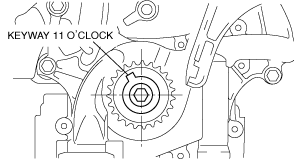
1. Turn the crankshaft clockwise so that the crankshaft keyway is in the 11 o’clock position. (This will position the No.1 cylinder at TDC.)
ac9wzw00003267
|
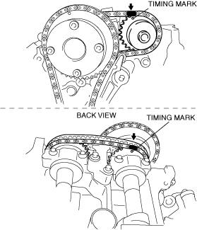
2. Mark the timing chain at the position of each timing sprocket timing mark.
azzjjw00000157
|
3. Mark the camshaft timing chain at the positions where it is aligned with each of the camshaft sprocket on both banks.
LH
ac9wzw00002222
|
RH
ac9wzw00002223
|
4. Remove the timing chain in the following order.
ac9wzw00002224
|
Variable Valve Timing Actuator Component Removal Note
1. Rotate the crankshaft counterclockwise until the keyway is in the 9 o'clock position.
ac9wzw00002225
|
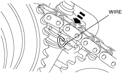
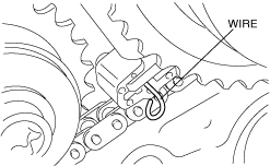
2. Slowly compress the camshaft timing chain tensioner (LH) piston by hand.
3. Insert an approx. 1.0 mm {0.039 in} thin wire or paper clip into the camshaft timing chain tensioner (LH) shown in the figure to hold the tensioner piston.
ac9wzw00002226
|
4. Install the SST onto the camshafts (LH).
ac9wzw00002227
|
ac9wzw00003272
|
5. Remove the variable valve timing actuator, camshaft timing chain and the exhaust camshaft sprocket of the LH bank as a single unit using the appropriate tools.
6. Remove the SST from the camshafts (LH).
7. Slowly compress the camshaft timing chain tensioner (RH) piston by hand.
8. Insert an approx. 1.0 mm {0.039 in} thin wire or paper clip into the camshaft timing chain tensioner (RH) shown in the figure to hold the tensioner piston.
ac9wzw00002229
|
9. Install the SST onto the camshafts (RH).
ac9wzw00002230
|
10. Remove the variable valve timing actuator, camshaft timing chain and the exhaust camshaft sprocket of the RH bank as a single unit using the appropriate tools.
11. Remove the SST from the camshafts (RH).
Variable Valve Timing Actuator Component Installation Note
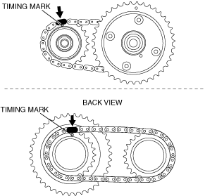
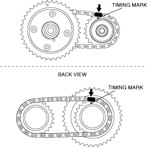
1. Align the alignment marks on the camshaft timing chain and both intake and exhaust side camshaft sprockets of both banks.
RH
ac9wzw00005860
|
LH
ac9wzw00002232
|
2. Install the variable valve timing actuator, camshaft timing chain and the exhaust camshaft sprocket of the RH bank as a single unit.
3. Remove the retaining wire inserted into the camshaft timing chain tensioner (RH).
ac9wzw00002233
|
ac9wzw00003272
|
4. Tighten the new camshaft sprocket (RH) installation bolts using the appropriate tools following 4 steps.
5. Install the variable valve timing actuator, camshaft timing chain and the exhaust camshaft sprocket of the LH bank as a single unit.
6. Remove the retaining wire inserted into the camshaft timing chain tensioner (LH).
ac9wzw00002234
|
7. Tighten the new camshaft sprocket (LH) installation bolts using the appropriate tools following 4 steps.
8. Turn the crankshaft clockwise so that the crankshaft keyway is in the 11 o’clock position. (This will position the No.1 cylinder at TDC.)
ac9wzw00002235
|
9. Follow the “TIMING CHAIN REMOVAL/INSTALLATION” procedure and install the timing chain. (See TIMING CHAIN REMOVAL/INSTALLATION [MZI-3.7].)