OIL PAN REMOVAL/INSTALLATION [MZI-3.7]


id0111e3800200


Removal

1.  Remove the battery and battery tray. (See BATTERY REMOVAL/INSTALLATION [MZI-3.7].)

2.  Remove the engine cover. (See ENGINE COVER REMOVAL/INSTALLATION [MZI-3.7].)

3.  Remove the dipstick.

4.  Remove the fresh-air duct and air cleaner component as a single unit. (See INTAKE-AIR SYSTEM REMOVAL/INSTALLATION [MZI-3.7].)

5.  Remove the resonance chamber. (See INTAKE-AIR SYSTEM REMOVAL/INSTALLATION [MZI-3.7].)

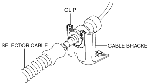
6.  Install the selector cable and clip to the bracket as shown in the figure.

ac9uuw00004512

7.  Remove the harness bracket from the transaxle.

ac9uuw00004513

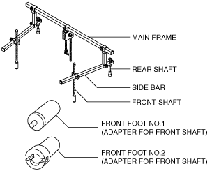
8.  Remove the following parts to install the SST.

(1)  The windshield wiper arm and blade. (See WINDSHIELD WIPER ARM AND BLADE REMOVAL/INSTALLATION.)
(2)  The cowl grille. (See COWL GRILLE REMOVAL/INSTALLATION.)
(3)  The cowl panel. (See COWL PANEL REMOVAL/INSTALLATION.)
(4)  The front cooler pipe installation bolt (position the front cooler pipe out of the way.).
ac9uuw00004514

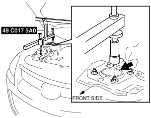
9.  Install the SST using the following procedure.

Caution
•  Refer to the SST instruction manual for the basic handing procedure.
ac9uuw00004515
Note
•  When installing the SST, adjust the position of each shaft so that they do not interfere with the vehicle body.
(1)  Install the right rear shaft of the SST to the bolt of the right shock absorber shown in the figure.
ac9uuw00004516
(2)  Install the left rear shaft of the SST to the bolt of the left shock absorber (Identical position to the right side).
(3)  Install the left/right front shaft of the SST with front foot No.2 to the bolt shown in the figure.
ac9uuw00004517
(4)  Adjust the positions of the SST side bars so that they are the same height (left and right) and horizontal.
(5)  Make sure each joint is securely tightened.

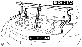
10.  Support the engine using the SSTs.

ac9uuw00004518

11.  Drain the engine oil into a container. (See ENGINE OIL REPLACEMENT [MZI-3.7].)

12.  Remove the oil filter. (See OIL FILTER REPLACEMENT [MZI-3.7].)

13.  Disconnect the oil cooler from the transaxle with the hose connected, and set it out of the way. (See OIL COOLER REMOVAL/INSTALLATION [AY6A-EL, AY6AX-EL].)

14.  Remove the following parts:

2WD
Note
•  Suspend the middle pipe using a cable.
4WD
Note
•  Suspend the presilencer using a cable.
6.  Front drive shaft (RH) (See FRONT DRIVE SHAFT REMOVAL/INSTALLATION.)

15.  Disconnect the propeller shaft from the transfer side. (4WD) (See PROPELLER SHAFT REMOVAL/INSTALLATION.)

16.  Remove the No.1 engine mount bracket installation bolts.

ac9uuw00004519

17.  Remove the No.1 engine mount rubber installation bolt and the No.1 engine mount. (4WD)

ac9uuw00004520

18.  Remove the transfer. (4WD) (See TRANSFER REMOVAL/INSTALLATION.)

19.  Remove the WU-TWC bracket (LH) installation bolt. (See EXHAUST SYSTEM REMOVAL/INSTALLATION [MZI-3.7].)

ac9uuw00004521
ac9uuw00004522

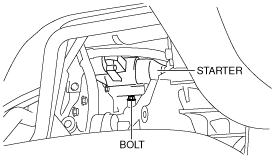
20.  Remove the starter installation bolt.

ac9uuw00004523

21.  Loosen the A/C compressor installation bolt shown in the figure.

Note
•  The A/C compressor installation bolt cannot be removed because it contacts the front crossmember.
ac9uuw00004524

22.  Remove the splash shield (RH).

23.  Remove the engine front cover installation bolts shown in the figure.

ac9uuw00004525

24.  Loose the transaxle installation bolt 2—3 mm {0.08—0.11 in} and disconnect the transaxle from the engine 2—3 mm {0.08—0.11 in}.

Caution
•  If the clearance between the engine and transaxle exceeds 3 mm {0.1 in}, the oil pump may pull out of the torque converter and the engine may not engage with the transaxle. Therefore, be careful not to exceed the 3 mm {0.1 in} clearance when disconnecting the engine from the transaxle.
•  If the clearance between the engine and transaxle exceeds 3 mm {0.1 in}, the dowel pin may pull out causing damage to the oil pump bushing. Therefore, be careful not to exceed the 3 mm {0.1 in} clearance when disconnecting the engine from the transaxle.
•  If the crankshaft is rotated with the engine disconnected from the transaxle, the oil pump may pull out of the torque converter and the engine may not engage with the transaxle.Therefore, do not rotate the crankshaft with the engine disconnected from the transaxle.
•  If the transaxle is tilted when disconnecting/tightening the engine and transaxle, the oil pump bushing may be damaged. Therefore, maintain the transaxle in a horizontal position when disconnecting/tightening the engine and transaxle.
ac9uuw00004526
ac9uuw00004527

25.  Remove in the order indicated in the table.

ac9uuw00004528

1
Oil pan
2
Oil strainer
3
O-ring


oil pan removal note

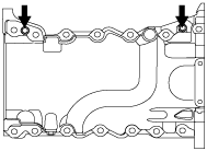
1.  Install two of the oil pan bolts temporarily into the two threaded holes in the oil pan.

ac9uuw00004529

2.  Alternately tighten the two bolts one turn at a time until the oil pan-to-cylinder block seal is released.

3.  Remove the oil pan.


Installation

Caution
•  Apply silicon sealant in a single, unbroken line.
•  Install the oil pan before the applied sealant starts to harden.
•  Using bolts with the old seal adhering could cause cracks in the cylinder block.
ac9uuw00004530

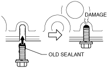
1.  Completely clean and remove any oil, dirt, sealant or other foreign material that may be adhering to the cylinder block and oil pan.

2.  When reusing the oil pan bolts, clean any old sealant from the bolts.

3.  Apply silicone sealant (Loctite 5900) to the oil pan along the inside of the bolt holes as shown in the figure.

ac9uuw00004531

Silicon sealant thickness
A: Approx. 3.0 mm {0.1 in}
B: 5.0—6.0 mm {0.20—0.23 in}
C: 10.0 mm {0.39 in}

4.  Apply the silicon sealant (Loctite 5900) to the engine front cover shown in the figure.

acmzzw00000108

Silicon sealant thickness
A: 2.5—3.5 mm {0.10—0.13 in}
B: 5.0—6.0 mm {0.20—0.23 in}

5.  Install the oil pan to the cylinder block.

(1)  Temporarily tighten the oil pan installation bolts.
(2)  Temporarily tighten the engine front cover installation bolts.
(3)  Tighten the oil pan installation bolts in the order shown in the figure.
ac9uuw00004533
Tightening torque
3.0 N·m {31 kgf·cm, 27 in·lbf}
(4)  Loosen the oil pan installation bolts 180 °.
(5)  Tighten the oil pan installation bolts in the order shown in the figure.
ac9uuw00004534
Tightening torque
Bolt A: 20—28 N·m {2.1—2.8 kgf·m, 15—20 ft·lbf}
Bolt B: 8.5—11.5 N·m {87—117 kgf·cm, 76—101 in·lbf}
(6)  Tighten the engine front cover installation bolts in the order in 2 steps in the order shown in the figure.
ac9uuw00004535
Tightening torque
1.  10 N·m {102 kgf·cm, 89 in·lbf}
2.  20—28 N·m {2.1—2.8 kgf·m, 15—20 ft·lbf}

6.  Install the splash shield (RH).

7.  Tighten the transaxle installation bolts.

Caution
•  If the clearance between the engine and transaxle exceeds 3 mm {0.1 in}, the oil pump may pull out of the torque converter and the engine may not engage with the transaxle. Therefore, be careful not to exceed the 3 mm {0.1 in} clearance when disconnecting the engine from the transaxle.
•  If the clearance between the engine and transaxle exceeds 3 mm {0.1 in}, the dowel pin may pull out causing damage to the oil pump bushing. Therefore, be careful not to exceed the 3 mm {0.1 in} clearance when disconnecting the engine from the transaxle.
•  If the crankshaft is rotated with the engine disconnected from the transaxle, the oil pump may pull out of the torque converter and the engine may not engage with the transaxle.Therefore, do not rotate the crankshaft with the engine disconnected from the transaxle.
•  If the transaxle is tilted when disconnecting/tightening the engine and transaxle, the oil pump bushing may be damaged. Therefore, maintain the transaxle in a horizontal position when disconnecting/tightening the engine and transaxle.
ac9uuw00004526
Tightening torque
37—52 N·m {3.8—5.3 kgf·m, 28—38 ft·lbf}

8.  Tighten the A/C compressor installation bolt shown in the figure.

ac9uuw00004536

Tightening torque
24—36 N·m {2.5—3.6 kgf·m, 18—26 ft·lbf}

9.  Tighten the starter installation bolt.

ac9uuw00004537

Tightening torque
38—52 N·m {3.9—5.3 kgf·m, 29—38 ft·lbf}

10.  Tighten the WU-TWC bracket (LH) installation bolt.

ac9uuw00004522
ac9uuw00004521

Tightening torque
17—23 N·m {1.8—2.3 kgf·m, 13—16 ft·lbf}

11.  Install the transfer. (4WD) (See TRANSFER REMOVAL/INSTALLATION.)

12.  Tighten bolt B to the specified torque after tightening bolt A to the specified torque.

ac9uuw00004519

Tightening torque
93.1—116.6 N·m {9.5—11.8 kgf·m, 68.7—85.9 ft·lbf}

13.  Tighten bolt C to the specified torque. (4WD)

Note
•  When replacing bolt C on the crossmember side, always replace it with a bolt of the same size as the removed one.
ac9uuw00004520
Tightening torque
M12 bolt : 93.1—116.6 N·m {9.5—11.8 kgf·m, 68.7—85.9 ft·lbf}
M14 bolt : 104.2—132.6 N·m {10.6—13.5 kgf·m, 76.9—97.8 ft·lbf}

14.  Install the propeller shaft. (4WD) (See PROPELLER SHAFT REMOVAL/INSTALLATION.)

15.  Install the following parts:

2WD
4WD
2.  Front drive shaft (RH) (See FRONT DRIVE SHAFT REMOVAL/INSTALLATION.)

16.  Install the oil cooler. (See OIL COOLER REMOVAL/INSTALLATION [AY6A-EL, AY6AX-EL].)

17.  Install the oil filter. (See OIL FILTER REPLACEMENT [MZI-3.7].)

18.  Remove the SST.

19.  Install the following parts:

(1)  The front cooler pipe bolt (position the front cooler pipe out of the way.).
ac9uuw00004514
Tightening torque
8—12 N·m {82—122 kgf·cm, 71—106 in·lbf}
(2)  The cowl panel. (See COWL PANEL REMOVAL/INSTALLATION.)
(3)  The cowl grille. (See COWL GRILLE REMOVAL/INSTALLATION.)
(4)  The windshield wiper arm and blade. (See WINDSHIELD WIPER ARM AND BLADE REMOVAL/INSTALLATION.)

20.  Install the harness bracket.

ac9uuw00004513

Tightening torque
8—10 N·m {82—101 kgf·cm, 71—88 in·lbf}

21.  Install the selector cable and clip to the bracket as shown in the figure.

ac9uuw00004538

22.  Install the resonance chamber. (See INTAKE-AIR SYSTEM REMOVAL/INSTALLATION [MZI-3.7].)

23.  Install the fresh-air duct and air cleaner component as a single unit. (See INTAKE-AIR SYSTEM REMOVAL/INSTALLATION [MZI-3.7].)

24.  Install the dipstick.

25.  Install the engine cover. (See ENGINE COVER REMOVAL/INSTALLATION [MZI-3.7].)

26.  Remove the battery and battery tray. (See BATTERY REMOVAL/INSTALLATION [MZI-3.7].)

27.  Refill with the specified type and amount of the engine oil. (See ENGINE OIL REPLACEMENT [MZI-3.7].)

28.  Start the engine and confirm that there is no oil leakage.

•  If there is oil leakage, repair or replace the applicable part.

29.  Inspect the oil level. (See ENGINE OIL LEVEL INSPECTION [MZI-3.7].)