|
ac9wzw00000119
DSC/RSC HU/CM REMOVAL/INSTALLATION [R.H.D.]
id0418008163c5
1. Remove the battery and battery tray. (See BATTERY REMOVAL/INSTALLATION [MZI-3.7].)
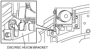
2. Remove the battery tray bracket as shown in the figure.
ac9wzw00000119
|
3. Remove the windshield wiper arm and blade. (See WINDSHIELD WIPER ARM AND BLADE REMOVAL/INSTALLATION.)
4. Remove the cowl grille. (See COWL GRILLE REMOVAL/INSTALLATION.)
5. Remove the wiper motor. (See WINDSHIELD WIPER MOTOR REMOVAL/INSTALLATION.)
6. Remove the cowl panel. (See COWL PANEL REMOVAL/INSTALLATION.)
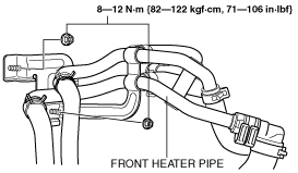
7. Remove the nuts as shown in the figure, and move the front heater pipe.
ac9wzw00000240
|
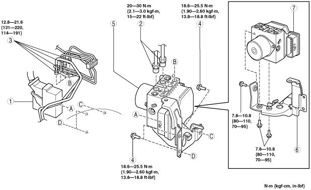
8. Remove in the order indicated in the table.
9. Install in the reverse order of removal.
10. After installation, add brake fluid, bleed the air, and inspect for fluid leakage. (See DSC/RSC HU AIR BLEEDING.) (See AIR BLEEDING.)
11. After installation, perform the DSC/RSC sensor initialization procedure. (See DSC/RSC SENSOR INITIALIZATION PROCEDURE.)
ac9wzw00000162
|
|
1
|
DSC/RSC HU/CM connector
|
|
2
|
Brake pipe (DSC/RSC HU/CM—master cylinder)
(See Brake Pipe Removal Note.)
(See Brake Pipe Installation Note.)
|
|
3
|
Brake pipe
(See Brake Pipe Removal Note.)
(See Brake Pipe Installation Note.)
|
|
4
|
Bolt
|
|
5
|
DSC/RSC HU/CM component
|
|
6
|
DSC/RSC HU/CM bracket
|
|
7
|
DSC/RSC HU/CM
|
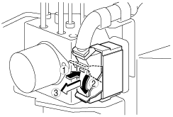
DSC/RSC HU/CM Connector Removal Note
1. Remove the DSC/RSC HU/CM connector using the following procedure:
ac9uuw00001269
|
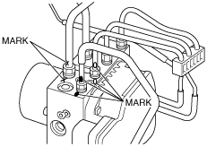
Brake Pipe Removal Note
1. Place an alignment mark on the brake pipe and DSC/RSC HU/CM.
ac9uuw00001325
|
2. Apply protective tape to the DSC/RSC HU/CM connector to prevent brake fluid from entering.
3. Remove the brake pipe.
DSC/RSC HU/CM Component Installation Note
1. Insert the DSC/RSC HU/CM bracket tab to the vehicle frame hole as shown in the figure.
ac9uuw00002274
|
2. Install the DSC/RSC HU/CM component.
Brake Pipe Installation Note
1. Align the marks made before removal and install the brake pipe to the DSC/RSC HU/CM and brake pipe joint referring to the figure.
ac9uuw00001332
|
2. Tighten the brake pipe to the specified torque using the commercially available flare nut wrench.
DSC/RSC HU/CM Connector Installation Note
1. Install the DSC/RSC HU/CM connector using the following procedure:
ac9uuw00001270
|
2. Verify that the DSC/RSC HU/CM connector is installed securely.