|
1
|
VERIFY PCM DTCs
• Retrieve the PCM DTCs using the M-MDS.
• Are any DTCs displayed?
|
Yes
|
Repair or replace the malfunctioning part according to the applicable DTC troubleshooting.
|
|
No
|
Go to the next step.
|
|
2
|
INSPECT BATTERY
• Is there any malfunction?
|
Yes
|
Recharge or replace the battery, then go to Step 12.
|
|
No
|
Go to the next step.
|
|
3
|
INSPECT GENERATOR
• Is there any malfunction?
|
Yes
|
Replace the generator, then go to Step 12.
|
|
No
|
Go to the next step.
|
|
4
|
INSPECT BCM CONNECTOR
• Turn the ignition switch to the OFF position.
• Disconnect the negative battery cable.
• Disconnect the BCM connector.
• Inspect the connector engagement and connection condition and inspect the terminals for damage, deformation, corrosion, or disconnection.
• Is there any malfunction?
|
Yes
|
Repair or replace the connector, then go to Step 12.
|
|
No
|
Go to the next step.
|
|
5
|
VERIFY IF MALFUNCTION CAUSE IS IGNITION SWITCH CIRCUIT OR OTHER
• Verify that the BCM connector is disconnected.
• Reconnect the negative battery cable.
• Turn the ignition switch to the ON position.
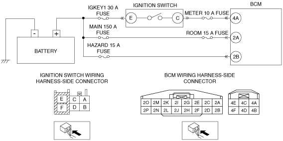
• Measure the voltage at the BCM terminal 4A (wiring harness-side).
• Is the voltage B+?
|
Yes
|
Go to Step 11.
|
|
No
|
Go to the next step.
|
|
6
|
INSPECT IGNITION SWITCH CONNECTOR
• Turn the ignition switch to the OFF position.
• Disconnect the negative battery cable.
• Disconnect the ignition switch connector.
• Inspect the connector engagement and connection condition and inspect the terminals for damage, deformation, corrosion, or disconnection.
• Is there any malfunction?
|
Yes
|
Repair or replace the connector, then go to Step 12.
|
|
No
|
Go to the next step.
|
|
7
|
VERIFY BCM POWER SUPPLY VOLTAGE
• Verify that the BCM and ignition switch connectors are disconnected.
• Reconnect the negative battery cable.
• Measure the voltage at the ignition switch terminal E (wiring harness-side).
• Is the voltage B+?
|
Yes
|
Go to the next step.
|
|
No
|
Inspect the IGKEY1 30 A fuse.
• If a fuse is burnt out:
-
― Repair or replace the wiring harness which has a short to ground.
― Replace the fuse.
• If a fuse is damaged:
-
― Replace the damaged fuse.
• If a fuse is normal:
-
― Repair or replace the wiring harness which has an open circuit.
Go to Step 12.
|
|
8
|
INSPECT IGNITION SWITCH
• Inspect the ignition switch.
• Is there any malfunction?
|
Yes
|
Replace the ignition switch, then go to Step 12.
|
|
No
|
Go to the next step.
|
|
9
|
INSPECT FOR SHORT TO GROUND IN IGNITION SWITCH CIRCUIT
• Verify that the BCM and ignition switch connectors are disconnected.
• Disconnect the negative battery cable.
• Inspect for continuity between ignition switch terminal C (wiring harness-side) and body ground.
• Is there continuity?
|
Yes
|
Repair or replace the wiring harness which has a short to ground, then go to Step 12.
|
|
No
|
Go to the next step.
|
|
10
|
INSPECT FOR OPEN CIRCUIT IN IGNITION SWITCH CIRCUIT
• Verify that the BCM and ignition switch connectors are disconnected.
• Inspect for continuity between ignition switch terminal C (wiring harness-side) and BCM terminal 4A (wiring harness-side).
• Is there continuity?
|
Yes
|
Go to the next step.
|
|
No
|
Repair or replace the wiring harness which has an open circuit, then go to Step 12.
|
|
11
|
VERIFY BCM POWER SUPPLY VOLTAGE
• Verify that the BCM connector is disconnected.
• Reconnect the negative battery cable.
• Measure the voltage at the following terminals (wiring harness-side):
-
― BCM terminal 2A
― BCM terminal 2B
• Is the voltage B+?
|
Yes
|
Go to the next step.
|
|
No
|
Inspect the following fuse:
• MAIN 150 A fuse
• ROOM 15 A fuse
• HAZARD 15 A fuse
-
― If a fuse is burnt out:
-
• Repair or replace the wiring harness which has a short to ground.
• Replace the fuse.
-
― If a fuse is damaged:
-
• Replace the damaged fuse.
-
― If a fuse is normal:
-
• Repair or replace the wiring harness which has an open circuit.
Go to the next step.
|
|
12
|
VERIFY DTC TROUBLESHOOTING COMPLETED
• Make sure to reconnect all disconnected connectors.
• Reconnect the negative battery cable.
• Clear the DTC for the BCM using the M-MDS.
• Retrieve the BCM DTCs using the M-MDS.
• Is the same DTC displayed?
|
Yes
|
Repeat the inspection from Step 1.
• If the malfunction recurs, replace the BCM.
Go to the next step.
|
|
No
|
Go to the next step.
|
|
13
|
VERIFY IF OTHER DTCs DISPLAYED
• Are any other DTCs displayed?
|
Yes
|
Repair or replace the malfunctioning part according to the applicable DTC troubleshooting.
|
|
No
|
DTC troubleshooting completed.
|