DTC C1295, C1307, C1441, C1442, C1443, C1444, C144A, C144B, C144C, C144D [BCM]
id0902f5841200
Description |
DTC C1295 • Steering angle sensor internal malfunction
DTC C1307 • Steering angle sensor encoder ring defective
DTC C1441/C1443 • Steering angle sensor A signal circuit malfunction
DTC C1442/C1444 • Steering angle sensor B signal circuit malfunction
DTC C144A/C144C • Steering angle sensor C signal circuit malfunction
DTC C144B/C144D • Steering angle sensor Z signal circuit malfunction
|
---|---|
Detection condition
|
DTC C1295
• BCM detects the steering angle sensor internal abnormality (signal overflow).
DTC C1307
• BCM detects the steering angle sensor internal abnormality (signal jump).
DTC C1441
• Open circuit in steering angle sensor A signal circuit.
DTC C1442
• Open circuit in steering angle sensor B signal circuit.
DTC C1443
• Short to ground in steering angle sensor A signal circuit.
DTC C1444
• Short to ground in steering angle sensor B signal circuit.
DTC C144A
• Short to ground in steering angle sensor C signal circuit.
DTC C144B
• Short to ground in steering angle sensor Z signal circuit.
DTC C144C
• Open circuit in steering angle sensor C signal circuit.
DTC C144D
• Open circuit in steering angle sensor Z signal circuit.
|
Possible cause
|
• Excessive grease is adhering to solid disc for steering angle detection
• Steering wheel is off-center.
• Steering angle sensor connector or terminal malfunction
• BCM connector or terminal malfunction
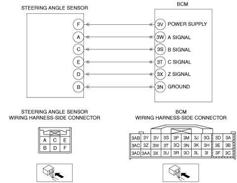
• Short to ground in wiring harness between the following terminals:
• Short to power supply in wiring harness between the following terminals:
• Open circuit in wiring harness between the following terminals:
• Improper installation or positioning of the steering angle sensor
• Steering angle sensor malfunction
• BCM malfunction
|
![]() |
Diagnostic procedure
Step |
Inspection |
Action |
|
---|---|---|---|
1
|
INSPECT SOLID DISC FOR STEERING ANGLE DETECTION
• Visually inspect the solid disc for the steering angle detection.
• Is excessive grease adhering?
|
Yes
|
Wipe off excessive grease using a cloth, then go to Step 10.
|
No
|
Go to the next step.
|
||
2
|
INSPECT STEERING WHEEL FOR OFF-CENTER
• Drive the vehicle and inspect the steering wheel position while driving in a straight line.
• Is the steering wheel off-center?
|
Yes
|
Inspect and adjust the front wheel alignment to correct the steering wheel alignment, then go to Step 10.
(See FRONT WHEEL ALIGNMENT.)
|
No
|
Go to the next step.
|
||
3
|
INSPECT STEERING ANGLE SENSOR CONNECTOR
• Turn the ignition switch to the OFF position.
• Disconnect the negative battery cable.
• Disconnect the steering angle sensor connector.
• Inspect the connector engagement and connection condition and inspect the terminals for damage, deformation, corrosion, or disconnection.
• Is there any malfunction?
|
Yes
|
Repair or replace the connector, then go to Step 10.
|
No
|
Go to the next step.
|
||
4
|
INSPECT BCM CONNECTOR
• Disconnect the BCM connector.
• Inspect the connector engagement and connection condition and inspect the terminals for damage, deformation, corrosion, or disconnection.
• Is there any malfunction?
|
Yes
|
Repair or replace the connector, then go to Step 10.
|
No
|
Go to the next step.
|
||
5
|
INSPECT FOR SHORT TO GROUND IN STEERING ANGLE SENSOR CIRCUIT
• Verify that the steering angle sensor and BCM connectors are disconnected.
• Inspect for continuity between the following terminals (wiring harness-side) and body ground:
• Is there continuity?
|
Yes
|
Repair or replace the wiring harness which has a short to ground, then go to Step 10.
|
No
|
Go to the next step.
|
||
6
|
INSPECT FOR SHORT TO POWER SUPPLY IN STEERING ANGLE SENSOR CIRCUIT
• Verify that the steering angle sensor and BCM connectors are disconnected.
• Reconnect the negative battery cable.
• Turn the ignition switch to the ON position.
• Measure the voltage at the following terminals (wiring harness-side):
• Is the voltage 0 V?
|
Yes
|
Go to the next step.
|
No
|
Repair or replace the wiring harness which has a short to power supply, then go to Step 10.
|
||
7
|
INSPECT FOR OPEN CIRCUIT IN STEERING ANGLE SENSOR CIRCUIT
• Verify that the steering angle sensor and BCM connectors are disconnected.
• Turn the ignition switch to the OFF position.
• Disconnect the negative battery cable.
• Inspect for continuity between the following terminals (wiring harness-side):
• Is there continuity?
|
Yes
|
Go to the next step.
|
No
|
Repair or replace the wiring harness which has an open circuit, then go to Step 10.
|
||
8
|
INSPECT FOR IMPROPER INSTALLATION OF STEERING ANGLE SENSOR
• Inspect the installation of the steering angle sensor.
• Is there any malfunction?
|
Yes
|
Repair installation or replace the steering angle sensor, then go to Step 10.
|
No
|
Go to the next step.
|
||
9
|
INSPECT STEERING ANGLE SENSOR
• Inspect the steering angle sensor.
• Is there any malfunction?
|
Yes
|
Replace the steering angle sensor, then go to the next step.
|
No
|
Go to the next step.
|
||
10
|
VERIFY DTC TROUBLESHOOTING COMPLETED
• Make sure to reconnect all disconnected connectors.
• Reconnect the negative battery cable.
• Clear the DTC for the BCM using the M-MDS.
(See CLEARING DTC [BCM].)
• Drive the vehicle at 10 km/h {6.2 mph} or more.
• Retrieve the BCM DTCs using the M-MDS.
(See DTC INSPECTION [BCM].)
• Is the same DTC displayed?
|
Yes
|
Repeat the inspection from Step 1.
• If the malfunction recurs, replace the BCM.
Go to the next step.
|
No
|
Go to the next step.
|
||
10
|
VERIFY IF OTHER DTCs DISPLAYED
• Are any other DTCs displayed?
|
Yes
|
Repair or replace the malfunctioning part according to the applicable DTC troubleshooting.
(See DTC TABLE [BCM].)
|
No
|
DTC troubleshooting completed.
|