|
1
|
VERIFY IF MALFUNCTION CAUSE IS FRONT DOOR LOCK-LINK SWITCH (PASSENGER-SIDE) CIRCUIT, REAR DOOR LOCK-LINK SWITCH (LH) CIRCUIT, (RH) CIRCUIT OR BCM
• Operate the door lock-link switch to lock and unlock.
• Do all door lock-link switch operate correctly?
|
Yes
|
Go to Step 20.
|
|
No
|
Front door lock-link switch (passenger-side) does not operate correctly:
• Go to the next step.
Rear door lock-link switch (LH) does not operate correctly:
• Go to Step 8.
Rear door lock-link switch (RH) does not operate correctly:
• Go to Step 14.
All door lock-link switches do not operate correctly:
• Go to Step 20.
|
|
2
|
INSPECT FRONT DOOR LATCH AND LOCK ACTUATOR (PASSENGER-SIDE) CONNECTOR
• Turn the ignition switch to the OFF position.
• Disconnect the negative battery cable.
• Disconnect the front door latch and lock actuator (passenger-side) connector.
• Inspect the connector engagement and connection condition and inspect the terminals for damage, deformation, corrosion, or disconnection.
• Is there any malfunction?
|
Yes
|
Repair or replace the connector, then go to Step 20.
|
|
No
|
Go to the next step.
|
|
3
|
VERIFY IF MALFUNCTION CAUSE IS FRONT DOOR LOCK-LINK SWITCH (PASSENGER-SIDE) POWER SUPPLY CIRCUIT OR GROUND CIRCUIT
• Verify that the front door latch and lock actuator (passenger-side) connector is disconnected.
• Reconnect the negative battery cable.
• Measure the voltage at the following terminal (wiring harness-side):
-
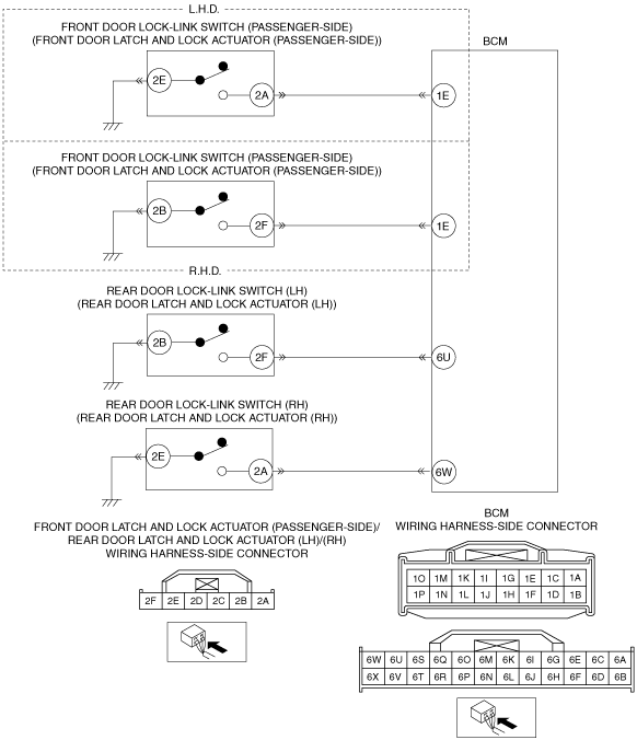
― Front door latch and lock actuator (passenger-side) terminal 2A (L.H.D.)
― Front door latch and lock actuator (passenger-side) terminal 2F (R.H.D.)
• Is the voltage 0 V?
|
Yes
|
A malfunction in power supply circuit can be considered.
• Go to Step 6.
|
|
No
|
A malfunction in ground circuit can be considered.
• Go to the next step.
|
|
4
|
INSPECT FOR OPEN CIRCUIT IN FRONT DOOR LOCK-LINK SWITCH (PASSENGER-SIDE) GROUND CIRCUIT
• Verify that the front door latch and lock actuator (passenger-side) connector is disconnected.
• Disconnect the negative battery cable.
• Inspect for continuity between the following terminal (wiring harness-side) and body ground:
-
― Front door latch and lock actuator (passenger-side) terminal 2E (L.H.D.)
― Front door latch and lock actuator (passenger-side) terminal 2B (R.H.D.)
• Is there continuity?
|
Yes
|
Go to the next step.
|
|
No
|
Repair or replace the wiring harness which has an open circuit, then go to Step 20.
|
|
5
|
INSPECT FRONT DOOR LOCK-LINK SWITCH (PASSENGER-SIDE)
• Inspect the front door lock-link switch (passenger-side).
• Is there any malfunction?
|
Yes
|
Replace the front door latch and lock actuator (passenger-side), then go to Step 20.
|
|
No
|
Go to Step 20.
|
|
6
|
INSPECT BCM CONNECTOR
• Disconnect the negative battery cable.
• Disconnect the BCM connector.
• Inspect the connector engagement and connection condition and inspect the terminals for damage, deformation, corrosion, or disconnection.
• Is there any malfunction?
|
Yes
|
Repair or replace the connector, then go to Step 20.
|
|
No
|
Go to the next step.
|
|
7
|
VERIFY IF MALFUNCTION CAUSE IS BCM OR FRONT DOOR LOCK-LINK SWITCH (PASSENGER-SIDE) POWER SUPPLY CIRCUIT
• Reconnect the BCM connector.
• Reconnect the negative battery cable.
• Measure the voltage at the BCM terminal 1E (wiring harness-side).
• Is the voltage 0 V?
|
Yes
|
A malfunction in BCM can be considered.
• Go to Step 20.
|
|
No
|
A malfunction in power supply circuit can be considered.
• Repair or replace the wiring harness which has an open circuit, then go to Step 20.
|
|
8
|
INSPECT REAR DOOR LATCH AND LOCK ACTUATOR (LH) CONNECTOR
• Turn the ignition switch to the OFF position.
• Disconnect the negative battery cable.
• Disconnect the rear door latch and lock actuator (LH) connector.
• Inspect the connector engagement and connection condition and inspect the terminals for damage, deformation, corrosion, or disconnection.
• Is there any malfunction?
|
Yes
|
Repair or replace the connector, then go to Step 20.
|
|
No
|
Go to the next step.
|
|
9
|
VERIFY IF MALFUNCTION CAUSE IS REAR DOOR LOCK-LINK SWITCH (LH) POWER SUPPLY CIRCUIT OR GROUND CIRCUIT
• Verify that the rear door latch and lock actuator (LH) connector is disconnected.
• Reconnect the negative battery cable.
• Measure the voltage at the rear door latch and lock actuator (LH) terminal 2F (wiring harness-side).
• Is the voltage 0 V?
|
Yes
|
A malfunction in power supply circuit can be considered.
• Go to Step 12.
|
|
No
|
A malfunction in ground circuit can be considered.
• Go to the next step.
|
|
10
|
INSPECT FOR OPEN CIRCUIT IN REAR DOOR LOCK-LINK SWITCH (LH) GROUND CIRCUIT
• Verify that the rear door latch and lock actuator (LH) connector is disconnected.
• Disconnect the negative battery cable.
• Inspect for continuity between rear door latch and lock actuator (LH) terminal 2B (wiring harness-side) and body ground.
• Is there continuity?
|
Yes
|
Go to the next step.
|
|
No
|
Repair or replace the wiring harness which has an open circuit, then go to Step 20.
|
|
11
|
INSPECT REAR DOOR LOCK-LINK SWITCH (LH)
• Inspect the rear door lock-link switch (LH).
• Is there any malfunction?
|
Yes
|
Replace the rear door latch and lock actuator (LH), then go to Step 20.
|
|
No
|
Go to Step 20.
|
|
12
|
INSPECT BCM CONNECTOR
• Disconnect the negative battery cable.
• Disconnect the BCM connector.
• Inspect the connector engagement and connection condition and inspect the terminals for damage, deformation, corrosion, or disconnection.
• Is there any malfunction?
|
Yes
|
Repair or replace the connector, then go to Step 20.
|
|
No
|
Go to the next step.
|
|
13
|
VERIFY IF MALFUNCTION CAUSE IS BCM OR REAR DOOR LOCK-LINK SWITCH (LH) POWER SUPPLY CIRCUIT
• Reconnect the BCM connector.
• Reconnect the negative battery cable.
• Measure the voltage at the BCM terminal 6U (wiring harness-side).
• Is the voltage 0 V?
|
Yes
|
A malfunction in BCM can be considered.
• Go to Step 20.
|
|
No
|
A malfunction in power supply circuit can be considered.
• Repair or replace the wiring harness which has an open circuit, then go to Step 20.
|
|
14
|
INSPECT REAR DOOR LATCH AND LOCK ACTUATOR (RH) CONNECTOR
• Turn the ignition switch to the OFF position.
• Disconnect the negative battery cable.
• Disconnect the rear door latch and lock actuator (RH) connector.
• Inspect the connector engagement and connection condition and inspect the terminals for damage, deformation, corrosion, or disconnection.
• Is there any malfunction?
|
Yes
|
Repair or replace the connector, then go to Step 20.
|
|
No
|
Go to the next step.
|
|
15
|
VERIFY IF MALFUNCTION CAUSE IS REAR DOOR LOCK-LINK SWITCH (RH) POWER SUPPLY CIRCUIT OR GROUND CIRCUIT
• Verify that the rear door latch and lock actuator (RH) connector is disconnected.
• Reconnect the negative battery cable.
• Measure the voltage at the rear door latch and lock actuator (RH) terminal 2A (wiring harness-side).
• Is the voltage 0 V?
|
Yes
|
A malfunction in power supply circuit can be considered.
• Go to Step 18.
|
|
No
|
A malfunction in ground circuit can be considered.
• Go to the next step.
|
|
16
|
INSPECT FOR OPEN CIRCUIT IN REAR DOOR LOCK-LINK SWITCH (RH) GROUND CIRCUIT
• Verify that the rear door latch and lock actuator (RH) connector is disconnected.
• Disconnect the negative battery cable.
• Inspect for continuity between rear door latch and lock actuator (RH) terminal 2E (wiring harness-side) and body ground.
• Is there continuity?
|
Yes
|
Go to the next step.
|
|
No
|
Repair or replace the wiring harness which has an open circuit, then go to Step 20.
|
|
17
|
INSPECT REAR DOOR LOCK-LINK SWITCH (RH)
• Inspect the rear door lock-link switch (RH).
• Is there any malfunction?
|
Yes
|
Replace the rear door latch and lock actuator (RH), then go to Step 20.
|
|
No
|
Go to Step 20.
|
|
18
|
INSPECT BCM CONNECTOR
• Disconnect the negative battery cable.
• Disconnect the BCM connector.
• Inspect the connector engagement and connection condition and inspect the terminals for damage, deformation, corrosion, or disconnection.
• Is there any malfunction?
|
Yes
|
Repair or replace the connector, then go to Step 20.
|
|
No
|
Go to the next step.
|
|
19
|
VERIFY IF MALFUNCTION CAUSE IS BCM OR REAR DOOR LOCK-LINK SWITCH (RH) POWER SUPPLY CIRCUIT
• Reconnect the BCM connector.
• Reconnect the negative battery cable.
• Measure the voltage at the BCM terminal 6W (wiring harness-side).
• Is the voltage 0 V?
|
Yes
|
A malfunction in BCM can be considered.
• Go to the next step.
|
|
No
|
A malfunction in power supply circuit can be considered.
• Repair or replace the wiring harness which has an open circuit, then go to the next step.
|
|
20
|
VERIFY DTC TROUBLESHOOTING COMPLETED
• Make sure to reconnect all disconnected connectors.
• Reconnect the negative battery cable.
• Clear the DTC for the BCM using the M-MDS.
• Retrieve the BCM DTCs using the M-MDS.
• Is the same DTC displayed?
|
Yes
|
Repeat the inspection from Step 1.
• If the malfunction recurs, replace the BCM.
Go to the next step.
|
|
No
|
Go to the next step.
|
|
21
|
VERIFY IF OTHER DTCs DISPLAYED
• Are any other DTCs displayed?
|
Yes
|
Repair or replace the malfunctioning part according to the applicable DTC troubleshooting.
|
|
No
|
DTC troubleshooting completed.
|