 |
ac9wzw00002696
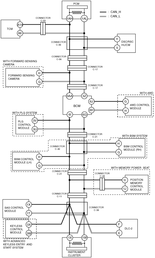
M-MDS AND VEHICLE NOT COMMUNICATING [MULTIPLEX COMMUNICATION SYSTEM (R.H.D.)]
id0902j4037400
Detection Condition
Possible Causes
Wiring Diagram
ac9wzw00002696
|
Diagnostic Procedure
|
Step |
Inspection |
Action |
|
|---|---|---|---|
|
1
|
VERIFICATION BEFORE SERVICING
• Is there communication between the M-MDS and vehicle?
|
Yes
|
Go to the next step.
|
|
No
|
Go back to FOREWORD [MULTIPLEX COMMUNICATION SYSTEM.
|
||
|
2
|
VERIFY THAT M-MDS AND DLC-2 ARE CONNECTED
• Verify the connection condition between the M-MDS and DLC-2.
• Are the connector terminals normal without damage, deformation, corrosion, or disconnection?
|
Yes
|
Go to the next step.
|
|
No
|
Correct the connection condition, then go to Step 13.
|
||
|
3
|
VERIFY PCM POWER SUPPLY CONDITION
• Refer to the PCM terminal voltage table and inspect the terminal voltage and fuse condition.
(See PCM INSPECTION [MZI-3.7].)
• Is the power supply condition normal?
|
Yes
|
Go to the next step.
|
|
No
|
Repair or replace the fuse or wiring harness, then go to Step 13.
|
||
|
4
|
VERIFY PCM BODY GROUND CONDITION
• Inspect the PCM body ground wiring harness and ground point.
• Are the ground and ground point normal?
|
Yes
|
Go to the next step.
|
|
No
|
Repair or replace the wiring harness, then go to Step 13.
|
||
|
5
|
INSPECT PCM CONNECTOR TERMINAL
• Disconnect the negative battery cable.
• Disconnect the PCM connector.
• Are the PCM connector terminal normal without damage, deformation, corrosion, or disconnection?
|
Yes
|
Go to the next step.
|
|
No
|
Repair the connector terminal if necessary, then go to Step 13.
|
||
|
6
|
INSPECT PCM
• Disconnect the PCM connector.
• Measure the resistance between the following PCM connector terminals:
• Is the resistance 118—130 ohms?
|
Yes
|
Go to the next step.
|
|
No
|
Replace the PCM, then go to the next step.
|
||
|
7
|
VERIFY THAT THERE IS NO OPEN CIRCUIT IN CAN COMMUNICATION WIRING HARNESS
• Verify the continuity between the following terminals:
• Is there continuity?
|
Yes
|
Go to the next step.
|
|
No
|
There is an open circuit in the CAN communication wiring harness. Repair or replace it, then go to Step 13.
|
||
|
8
|
INSPECT CAN COMMUNICATION WIRING HARNESS IN BCM FOR OPEN CIRCUIT
• Verify the continuity between the following terminals:
• Is there continuity?
|
Yes
|
Go to the next step.
|
|
No
|
Replace the BCM which has an open circuit in the CAN communication wiring harness in the BCM, then go to Step 13.
|
||
|
9
|
VERIFY THAT THERE IS NO SHORT CIRCUIT IN CAN COMMUNICATION WIRING HARNESS
• Measure the resistance between the terminals.
• Is the resistance 60 ohms or less?
|
Yes
|
There is an open circuit in the CAN communication wiring harness. Repair or replace it, then go to Step 13.
|
|
No
|
Go to the next step.
|
||
|
10
|
VERIFY NO SHORT CIRCUIT TO GROUND IN CAN COMMUNICATION WIRING HARNESS
• Verify the continuity between the following terminals:
• Is there continuity?
|
Yes
|
There is a short circuit to ground in the CAN communication wiring harness. Repair or replace it, then go to Step 13.
|
|
No
|
Go to the next step.
|
||
|
11
|
VERIFY NO SHORT CIRCUIT TO POWER SUPPLY SYSTEM IN CAN COMMUNICATION WIRING HARNESS
• Verify the continuity between the following terminals:
• Is there continuity?
|
Yes
|
There is a short circuit to the power supply system in the CAN communication wiring harness. Repair or replace it, then go to Step 13.
|
|
No
|
Go to the next step.
|
||
|
12
|
INSPECT CAN-RELATED MODULES OTHER THAN PCM and BCM
• Remove only one of the CAN-related modules other than those related to the PCM and BCM.
• Connect the negative battery cable.
• Connect the M-MDS to the DLC-2.
• Does the M-MDS recognize the vehicle?
|
Yes
|
Replace the removed module.
|
|
No
|
Inspect all of the CAN-related modules other than those related to the PCM and BCM using the same procedure.
After inspecting all of the modules, go to the next step.
|
||
|
13
|
PERFORM VEHICLE IDENTIFICATION
• Connect the M-MDS to the DLC-2.
• Does the M-MDS recognize the vehicle?
|
Yes
|
DTC troubleshooting completed.
|
|
No
|
Replace the PCM, then go to the next step.
|
||
|
14
|
PERFORM VEHICLE IDENTIFICATION
• Connect the M-MDS to the DLC-2.
• Does the M-MDS recognize the vehicle?
|
Yes
|
DTC troubleshooting completed.
|
|
No
|
Replace the BCM.
|
||