DTC U0001:88, U0073, U0073:00 [MULTIPLEX COMMUNICATION SYSTEM (R.H.D.)]


id0902j4847500

DTC

U0001:88

Module communication error

U0073

CAN system communication error

U0073:00

CAN system communication error

DETECTION CONDITION
Warning
•  Perform the following on-board diagnosis according to FOREWORD [MULTIPLEX COMMUNICATION SYSTEM (R.H.D.)] troubleshooting procedure.
•  CAN system-related harness malfunction
•  CAN system-related module malfunction
POSSIBLE CAUSE
•  Open or short circuit in wiring harness
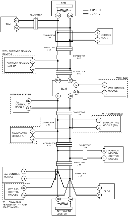
•  Malfunction of connectors between PCM, TCM, DSC/RSC HU/CM, forward sensing camera, BCM, 4WD control module, PLG control module, BSM control module (LH), BSM control module (RH), position memory control module, SAS control module, keyless control module and instrument cluster
•  PCM malfunction
•  TCM malfunction
•  DSC/RSC HU/CM malfunction
•  Forward sensing camera malfunction
•  BCM malfunction
•  4WD control module malfunction
•  PLG control module malfunction
•  BSM control module (LH) malfunction
•  BSM control module (RH) malfunction
•  Position memory control module malfunction
•  SAS control module malfunction
•  Keyless control module malfunction
•  Instrument cluster malfunction


Diagnostic procedure

Caution
•  When disconnecting the connector, verify that there is no looseness, damage, deformation, corrosion, or poor connection of the connector terminals.

Step

Inspection

Action

1
VERIFICATION BEFORE SERVICING
•  Are any DTCs, except the following, displayed?
―  U0001:88
―  U0073
―  U0073:00
Yes
No
Go to the next step.
2
INSPECTION OF CONTROL MODULE CONNECTOR OUTPUTTING DTCs
•  Inspect the terminal condition of the control module connector outputting DTCs and the mid-connector.
•  Are the connector terminals normal without damage, deformation, corrosion, or disconnection?
Yes
Go to the next step.
No
Repair or replace the connector, then go to Step 9.
3
INSPECTION OF POWER SUPPLY OF CONTROL MODULE OUTPUTTING DTCs
•  Refer to the terminal voltage table of the control module outputting DTCs or use the PID/data monitoring function to inspect the terminal voltage and fuse condition.
•  Is the power supply voltage normal?
Yes
Go to the next step.
No
Repair or replace the connector, then go to Step 9.
4
INSPECTION OF BODY GROUND CONDITION OF CONTROL MODULE OUTPUTTING DTCs
•  Inspect the body ground wires and ground point of the control module outputting DTCs.
•  Are the ground and ground point normal?
Yes
Go to the next step.
No
Repair or replace the connector, then go to Step 9.
5
CAN SYSTEM RELATED WIRING HARNESS INSPECTION
•  CAN system related wiring harness inspection:
―  Short to ground
―  Short to power supply
―  Short between twisted pair wiring harness
―  Open circuit
•  Is the wiring harness normal?
Yes
Go to the next step.
No
Repair or replace the connector, then go to Step 9.
6
INSPECT PCM
•  Disconnect the negative battery cable.
•  Disconnect the PCM connector.
•  Measure the resistance between the following PCM connector terminals:
―  Between terminal 1AH and terminal 1AL (part side)
•  Is the resistance 118—130 ohms?
Yes
Go to the next step.
No
Replace the PCM, then go to Step 9.
7
INSPECT INSTRUMENT CLUSTER
•  Disconnect the instrument cluster connector.
•  Measure the resistance between the following instrument cluster connector terminals:
―  Between terminal 1X and terminal 1W (part side)
•  Is the resistance 118—130 ohms?
Yes
Go to the next step.
No
Replace the instrument cluster, then go to Step 9.
8
CAN RELATED MODULE VERIFICATION
•  Remove only one of the CAN-related modules.
•  Clear DTCs using the M-MDS.
•  Inspect the DTCs of all modules using the M-MDS.
•  Are DTCs U0001:88, U0073, U0073:00 displayed?
Yes
Reinstall the removed module, remove another module and perform the same inspection. Inspect all of the CAN-related modules using the same procedure. After inspecting all of the modules, go to the next step.
No
Replace the removed module.
9
AFTER REPAIR VERIFICATION
•  Connect all of the modules.
•  Clear DTCs using the M-MDS.
•  Inspect the DTCs using the M-MDS.
•  Are DTCs displayed?
Yes
Perform the CAN system on-board diagnosis again according to the troubleshooting procedure
No
DTC troubleshooting completed.