INTERIOR LIGHT REMOVAL/INSTALLATION
id091800801500
1. Disconnect the negative battery cable.
2. Install in the reverse order of removal.
3. Remove the following parts:
- (1) A-pillar trim (See A-PILLAR TRIM REMOVAL/INSTALLATION.)
- (2) Front scuff plate inner (See FRONT SCUFF PLATE REMOVAL/INSTALLATION.)
- (3) Rear scuff plate inner (See REAR SCUFF PLATE REMOVAL/INSTALLATION.)
- (4) Front seat belt lower anchor installation bolt (Driver side) (See FRONT SEAT BELT REMOVAL/INSTALLATION.)
- (5) B-pillar lower trim (See B-PILLAR LOWER TRIM REMOVAL/INSTALLATION.)
- (6) Front seat belt upper anchor installation bolt (See FRONT SEAT BELT REMOVAL/INSTALLATION.)
- (7) B-pillar upper trim (See B-PILLAR UPPER TRIM REMOVAL/INSTALLATION.)
- (8) Trunk box (See TRUNK BOX REMOVAL/INSTALLATION.)
- (9) Seat side box (See SEAT SIDE BOX REMOVAL/INSTALLATION.)
- (10) Trunk end trim (See TRUNK END TRIM REMOVAL/INSTALLATION.)
- (11) Third-row seat (See THIRD-ROW SEAT REMOVAL/INSTALLATION.)
- (12) Third-row seat belt lower anchor installation bolt (See THIRD-ROW SEAT BELT REMOVAL/INSTALLATION.)
- (13) Trunk side trim (See TRUNK SIDE TRIM REMOVAL/INSTALLATION)
- (14) Roof side trim (See ROOF SIDE TRIM REMOVAL/INSTALLATION.)
- (15) Second-row seat belt upper anchor installation bolt (See SECOND-ROW SEAT BELT REMOVAL/INSTALLATION.)
- (16) C-pillar trim (See C-PILLAR TRIM REMOVAL/INSTALLATION.)
- (17) Third-row seat belt upper anchor installation bolt (See THIRD-ROW SEAT BELT REMOVAL/INSTALLATION.)
- (18) D-pillar trim (See D-PILLAR TRIM REMOVAL/INSTALLATION.)
- (19) Intruder sensor (with intruder sensor) (See INTRUDER SENSOR REMOVAL/INSTALLATION.)
- (20) Front map light (See FRONT MAP LIGHT REMOVAL/INSTALLATION.)
- (21) Sunvisor (See SUNVISOR REMOVAL/INSTALLATION.)
- (22) Assist handle (See ASSIST HANDLE REMOVAL/INSTALLATION.)
- (23) Headliner (See HEADLINER REMOVAL/INSTALLATION.)
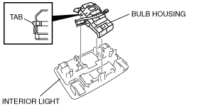
4. Detach the tab and remove the bulb housing.
-
Note
-
• The valve housing and the wiring harness have been integrated and attached to the headliner. When replacing the valve housing, remove the wiring harness which passes under the urethane by cutting the urethane.
5. Pull in the direction of the arrows and detach the tabs.
6. Remove the interior light.
7. Install in the reverse order of removal.
-
Note
-
• After installing the wiring harness, reinforce the urethane that was cut when removing the valve housing with vinyl tape.