Description
AUTOHOLD does not operate
Possible cause
• AUTOHOLD switch is stuck off
• Electrical supply unit (ESU) malfunction
• Open circuit in AUTOHOLD switch signal circuit
• Open circuit in AUTOHOLD switch ground circuit
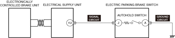
AUTOHOLD DOES NOT OPERATE [ELECTRONICALLY CONTROLLED BRAKE SYSTEM]
id040309071000
Outline
|
Description |
AUTOHOLD does not operate |
|
|---|---|---|
|
Possible cause
|
• AUTOHOLD switch is stuck off
• Electrical supply unit (ESU) malfunction
• Open circuit in AUTOHOLD switch signal circuit
• Open circuit in AUTOHOLD switch ground circuit
|
|
|
||
|
|
|
Diagnostic Procedure
|
Step
|
Inspection
|
Results
|
Action
|
|
1
|
VERIFY ELECTRONICALLY CONTROLLED BRAKE UNIT DTCs
• Verify the electronically controlled brake unit DTCs.
(See DTC INSPECTION.)
• Is a DTC displayed?
|
Yes
|
Repair the malfunctioning location according to the applicable DTC troubleshooting.
|
|
No
|
Go to the next step.
|
||
|
2
|
INSPECT ELECTRICAL SUPPLY UNIT (ESU) FOR MALFUNCTION
• Perform the DTC inspection for the body control module (BCM).
(See DTC INSPECTION.)
• Is an electrical supply unit (ESU) related DTC displayed?
|
Yes
|
Repair the malfunctioning location according to the applicable DTC troubleshooting.
|
|
No
|
Go to the next step.
|
||
|
3
|
INSPECT AUTOHOLD SWITCH FOR MALFUNCTION
• Inspect the applicable part.
(See AUTOHOLD SWITCH INSPECTION.)
• Is the AUTOHOLD switch normal?
|
Yes
|
Go to the next step.
|
|
No
|
Replace the electric parking brake switch and perform the repair completion verification.
|
||
|
4
|
INSPECT AUTOHOLD SWITCH GROUND CIRCUIT FOR OPEN CIRCUIT
• Inspect the applicable circuit for an open circuit.
(See CIRCUIT INSPECTION.)
• Is the circuit normal?
|
Yes
|
Go to the next step.
|
|
No
|
Repair or replace the malfunctioning location and perform the repair completion verification.
|
||
|
5
|
INSPECT AUTOHOLD SWITCH SIGNAL CIRCUIT FOR OPEN CIRCUIT
• Inspect the applicable circuit for an open circuit.
(See CIRCUIT INSPECTION.)
• Is the circuit normal?
|
Yes
|
Refer to the CAN (controller area network) malfunction diagnosis flow to inspect for a CAN communication error.
If the CAN communication is normal, perform the diagnosis from Step 1.
• If the malfunction has not been resolved, replace the electronically controlled brake unit.
Perform the repair completion verification.
|
|
No
|
Repair or replace the malfunctioning location and perform the repair completion verification.
|
||
|
Repair completion verification
|
VERIFY IF MALFUNCTION CAUSE IS CORRECTED
• Install/connect the part removed/disconnected during the troubleshooting procedure.
• Has the malfunction symptom been eliminated?
|
Yes
|
Complete the symptom troubleshooting.
Explain repair contents to customer.
|
|
No
|
Refer to the CAN (controller area network) malfunction diagnosis flow to inspect for a CAN communication error.
If the CAN communication is normal, perform the diagnosis from Step 1.
|