ANY OF THE FOLLOWING LIGHTS TURN ON. (ABS WARNING LIGHT, TCS/DSC OPERATION INDICATOR LIGHT, OR TCS OFF INDICATOR LIGHT) [ELECTRONICALLY CONTROLLED BRAKE SYSTEM]


id040309071600


Outline

Description

Any of the following lights turn on. (ABS warning light, TCS/DSC operation indicator light, or TCS OFF indicator light)

Possible cause
•  Electronically controlled brake unit detects malfunction (input/output device malfunction)
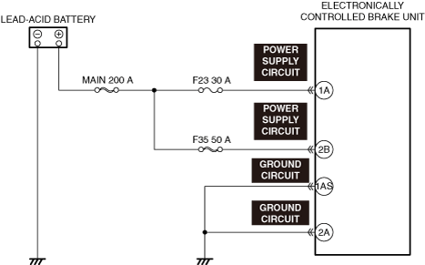
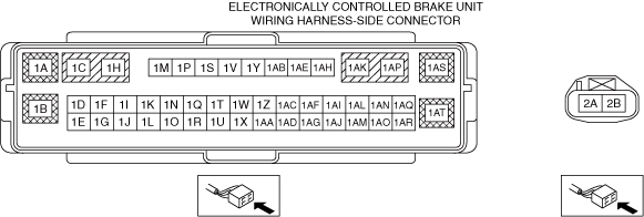
•  Electronically controlled brake unit connector is disconnected (circuit that turns on ABS warning light, TCS/DSC operation indicator light, brake system warning light, and TCS OFF indicator light if electronically controlled brake unit connector is disconnected)
•  Electronically controlled brake unit power supply voltage decreases
•  Poor ground in electronically controlled brake unit (If electronically controlled brake unit ground is not secured properly, ABS warning light, TCS/DSC operation indicator light, brake warning light, and TCS OFF indicator light turn on, but no DTC is output)
•  Electronically controlled brake unit does not activate
•  PCM detects malfunction
•  Error signal received from PCM
•  Body control module (BCM) detects malfunction
•  Communication error between electronically controlled brake unit and PCM
•  Communication error between electronically controlled brake unit and EPS control module
•  Communication error between electronically controlled brake unit and body control module (BCM)
•  Communication error between electronically controlled brake unit and Sophisticated Airbag Sensor (SAS) control module
•  Communication error between body control module (BCM) and instrument cluster
•  After replacing Sophisticated Airbag Sensor (SAS) control module, sensor initialization procedure for electronically controlled brake unit related parts not performed
•  After replacing electronically controlled brake unit, initialization procedure for brake fluid pressure sensor not performed
•  When replacing electronically controlled brake unit, configuration not performed (if configuration for electronically controlled brake unit is not performed, ABS warning light turns on)
•  Electronically controlled brake unit internal malfunction
•  Instrument cluster malfunction


Diagnostic Procedure

Step

Inspection

Results

Action

1
VERIFY ELECTRONICALLY CONTROLLED BRAKE UNIT DTCs
•  Verify the electronically controlled brake unit DTCs.
•  Is a DTC displayed?
Yes
Repair the malfunctioning location according to the applicable DTC troubleshooting.
No
Communication error is displayed on M-MDS screen:
•  Go to the next step.
Communication error is not displayed on M-MDS screen:
•  Go to Step 5.
2
INSPECT CONNECTION CONDITION FOR ELECTRONICALLY CONTROLLED BRAKE UNIT CONNECTOR
•  Verify the connection condition of the applicable connector.
•  Is the applicable connector connected correctly?
Yes
Go to the next step.
No
Connect the electronically controlled brake unit correctly again, then go to Step 5.
*3
INSPECT ELECTRONICALLY CONTROLLED BRAKE UNIT POWER SUPPLY CIRCUIT FOR SHORT TO GROUND AND OPEN CIRCUIT
•  Inspect the applicable circuit for a short to ground and open circuit.
•  Is the circuit normal?
Yes
Go to the next step.
No
Repair or replace the malfunctioning location and perform the repair completion verification.
*4
INSPECT ELECTRONICALLY CONTROLLED BRAKE UNIT GROUND CIRCUIT FOR SHORT TO POWER SUPPLY AND OPEN CIRCUIT
•  Inspect the applicable circuit for a short to power supply and open circuit.
•  Is the circuit normal?
Yes
Replace the electronically controlled brake unit and perform the repair completion verification. (Open circuit in electronically controlled brake unit internal circuit)
No
Repair or replace the malfunctioning location and perform the repair completion verification.
5
INSPECT PCM FOR MALFUNCTION
•  Perform the DTC inspection for the PCM.
•  Is a DTC displayed?
Yes
Repair the malfunctioning location according to the applicable DTC troubleshooting.
No
Go to the next step.
6
INSPECT BODY CONTROL MODULE (BCM) FOR MALFUNCTION
•  Perform the DTC inspection for the body control module (BCM).
•  Is a DTC displayed?
Yes
Repair the malfunctioning location according to the applicable DTC troubleshooting.
No
Go to the next step.
7
VERIFY SENSOR INITIALIZATION PROCEDURE PERFORMANCE CONDITION FOR ELECTRONICALLY CONTROLLED BRAKE UNIT RELATED PARTS
•  After replacing the electronically controlled brake unit and the Sophisticated Airbag Sensor (SAS) control module, has the sensor initialization procedure for the electronically controlled brake unit related parts been performed?
Yes
Go to the next step.
No
Perform the sensor initialization procedure for the electronically controlled brake unit related parts, and perform the repair completion verification.
8
VERIFY IF MALFUNCTION DUE TO NOT PERFORMING LOW-G SENSOR INITIALIZATION PROCEDURE
•  Verify if malfunction is due to not performing the low-G sensor (longitudinal-G sensor, lateral-G sensor) initialization procedure.
•  After replacing the electronically controlled brake unit and the Sophisticated Airbag Sensor (SAS) control module, has the low-G sensor initialization procedure been performed?
Yes
Go to the next step.
No
Perform the initialization procedures for the DSC longitudinal-G sensor and the DSC lateral-G sensor, and perform the repair completion verification.
9
VERIFY IF MALFUNCTION DUE TO NOT PERFORMING YAW RATE SENSOR INITIALIZATION PROCEDURE
•  Verify if malfunction is due to not performing the yaw rate sensor initialization procedure.
•  After replacing the electronically controlled brake unit and the Sophisticated Airbag Sensor (SAS) control module, has the yaw rate sensor initialization procedure been performed?
Yes
Go to the next step.
No
Perform the DSC yaw rate initialization procedure and perform the repair completion verification.
10
VERIFY IF MALFUNCTION CAUSE IS INSTRUMENT CLUSTER OR ELECTRONICALLY CONTROLLED BRAKE UNIT
•  Switch the main power ON (READY off).
•  After replacing the electronically controlled brake unit and the Sophisticated Airbag Sensor (SAS) control module, has the yaw rate sensor initialization procedure been performed?
Yes
Replace the electronically controlled brake unit and perform the repair completion verification.
No
Replace the instrument cluster and perform the repair completion verification.
Repair completion verification
VERIFY IF MALFUNCTION CAUSE IS CORRECTED
•  Install/connect the part removed/disconnected during the troubleshooting procedure.
•  Has the malfunction symptom been eliminated?
Yes
Complete the symptom troubleshooting.
Explain repair contents to customer.
No
Refer to the CAN (controller area network) malfunction diagnosis flow to inspect for a CAN communication error.
If the CAN communication is normal, perform the diagnosis from Step 1.

•  When performing an asterisked (*) troubleshooting inspection, first verify the damage and connection status of the connectors and terminals, then perform the inspection while shaking the wiring harness (cause of malfunction may be due to poor connection of connectors, terminals, or wiring harness). If there is a malfunction in the connectors or terminals, securely connect, repair, or perform replacement.